SOLIDWORKS Simulation-Using Symmetry
Geometric and Loading Symmetry
Some geometric shapes possess the property of symmetry. If a body, or an assembly of components, is able to be cut such that mirroring or patterning the remaining portion can be used to represent the entire body, then the body or assembly is said to be symmetric.
Symmetry in the loading application is also present if the loading can be cut such that mirroring or patterning of the remaining portion can be used to represent the actual loading condition.
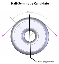
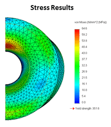
This example shows a geometric/loading scenario for which half-symmetry applies. Sometimes, the conditions will permit quarter- or eighth-symmetry. Also, for the case of most revolved features with uniform loading like internal pressure, axisymmetry will apply, which allows a pie-shaped cut to be used. Watch for these conditions when setting up FE analyses in SOLIDWORKS Simulation, since significant savings can be gained in the computer resources required to solve them.
SOLIDWORKS Simulation Model Setup
When symmetry applies, here’s how to set up your finite element model (FEM) using SOLIDWORKS Simulation after adding a physical cut to the geometry at the symmetry plane(s):
Static Analyses
For solid meshes, which have 3 degrees of freedom (DOF) per node, add the “symmetry” fixture type from the “Advanced” category to the cut face(s). For shell and beam meshes (6 DOF per node) use the “reference geometry” fixture type to restrain the out-of-plane translational DOF and the two in-plane rotational DOF.
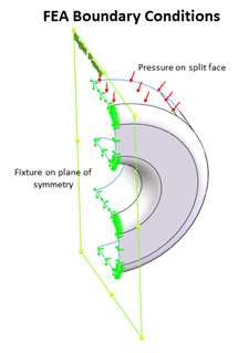
Loading applied to faces cut by the symmetry plane and applied on a “per area” basis, e.g., pressure, don’t have to be adjusted. Those applied to a face as a total value, e.g., force, are applied as a fraction of the total according to the amount of symmetry used, i.e., for ½ sym., use ½ of the total force. Symmetry conditions can also be set for bolt connectors in Simulation.
Thermal Analyses
For solid or shell meshes, no fixtures are needed at the symmetry plane as no heat transfer occurs across it, by default. Boundaries without specific conditions applied are treated as perfectly insulated. Apply the same temperature or heat flux loading as you would for the full model, but, similar to a force load in a static analysis, apply a fraction of the power loading according to the amount of symmetry used.
Learn more about SOLIDWORKS Simulation at one of our training courses or attend a SOLIDWORKS Webinar.
Author: Kurt Kurtin