Step By Step, Multiple Sequential Loads in SIMULIA for SOLIDWORKS
SOLIDWORKS Simulation Premium has always been able to apply multiple loads in sequence if the model does not move position. This means cold forming operations generally could not be simulated using multiple dies. With the introduction of SIMULIA for SOLIDWORKS now we can.
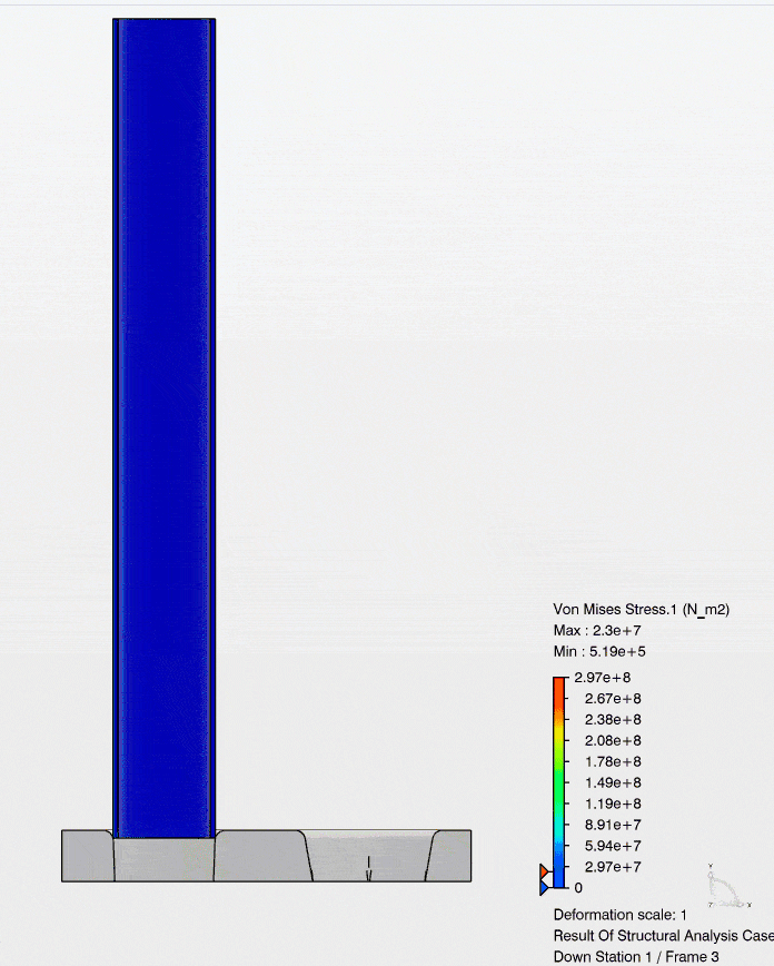
Let us look at the setup for the model and the desired output. In this model we have a metal tube, and a die set (Stations 1 & 2). The intention is to press the tube into the first die station forming the end of it to a smaller diameter (Step 1). Retract the tube from the first station (Step 2). Index the die to the second station and repeat the forming process at station 2 (Step 3).
![]()
STATIONS 1&2
![]()
Step 1
![]()
Step 2
![]()
Step 3
Using SIMULIA for SOLIDWORKS the application of analysis steps is a simple process. Navigating to the Procedures tab in the ribbon bar choose the Static Step icon. The new step property manager opens allowing you to name the step and adjust its properties.
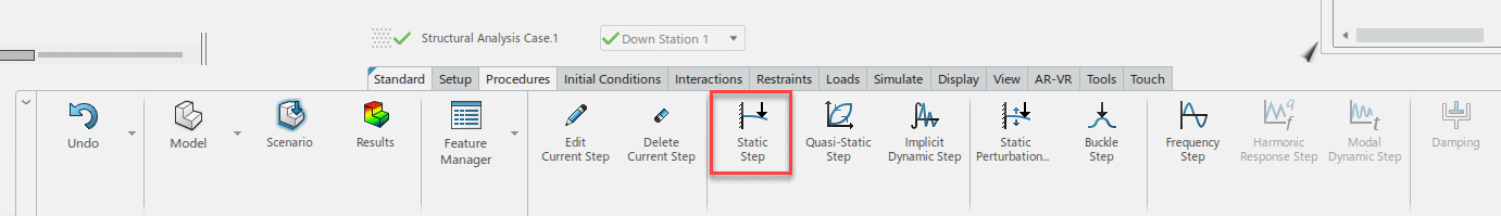
The new step can be found at the bottom of the screen, and in the Feature Manager window.
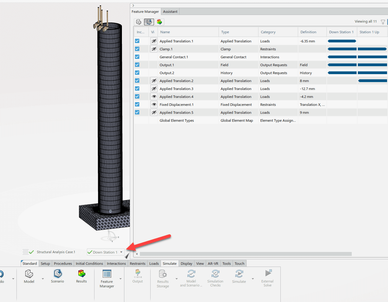
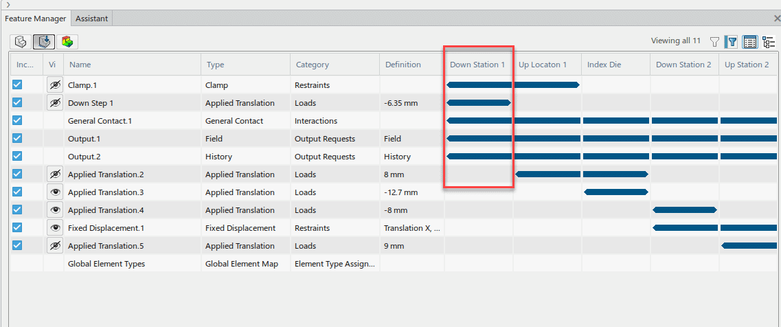
For each step the additional loads, and fixtures can be used in combination to achieve the desired output of the analysis.
In the Feature Manager tree boundary conditions can be turned off for specific steps. Highlighted below is step 1 of the forming sequence.
Once combined the result is a multi-step operation that keeps the stress from step to step. This method gives a complete picture of the loading process. Please see figure (Formed Tube End) for the cold forming result.
![]()
Formed Tube End
For more information reach out to your friendly CATI account manager. Check out the CATI YouTube page, and additional Simulation Blogs.
Robert Warren
Simulation Specialist, Application Engineer
Computer Aided Technology