Take Control Of Your Mesh
Do not let your mesh be too large or too small. Take control of your mesh, and generate a mesh that is just right.
Finite Element Analysis inherently is mesh dependent due to the fact that the software is discretizing (dividing up) a continuous problem into a finite number of little problems. If the user divides the problem up to coarsely the answer may be skewed. If the user divides up the problem to fine the solve time goes up. So what is an optimum mesh, and how do we best generate one?
Before we answer the previous question, let us discuss why we are concerned with a proper mesh. Because FEA is a numerical approximation and mesh dependent the analyst needs to verify that the results being presented are accurate. This is done through convergence. Convergence is the practice of refining the mesh to converge on a result value. Usually stress. When a model is seen as converged the results are considered valid. If you would like to know more please check out a previous blog regarding Convergence and Divergence.
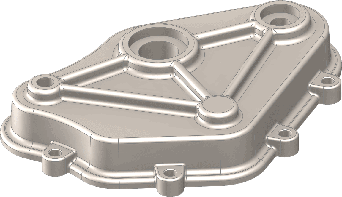
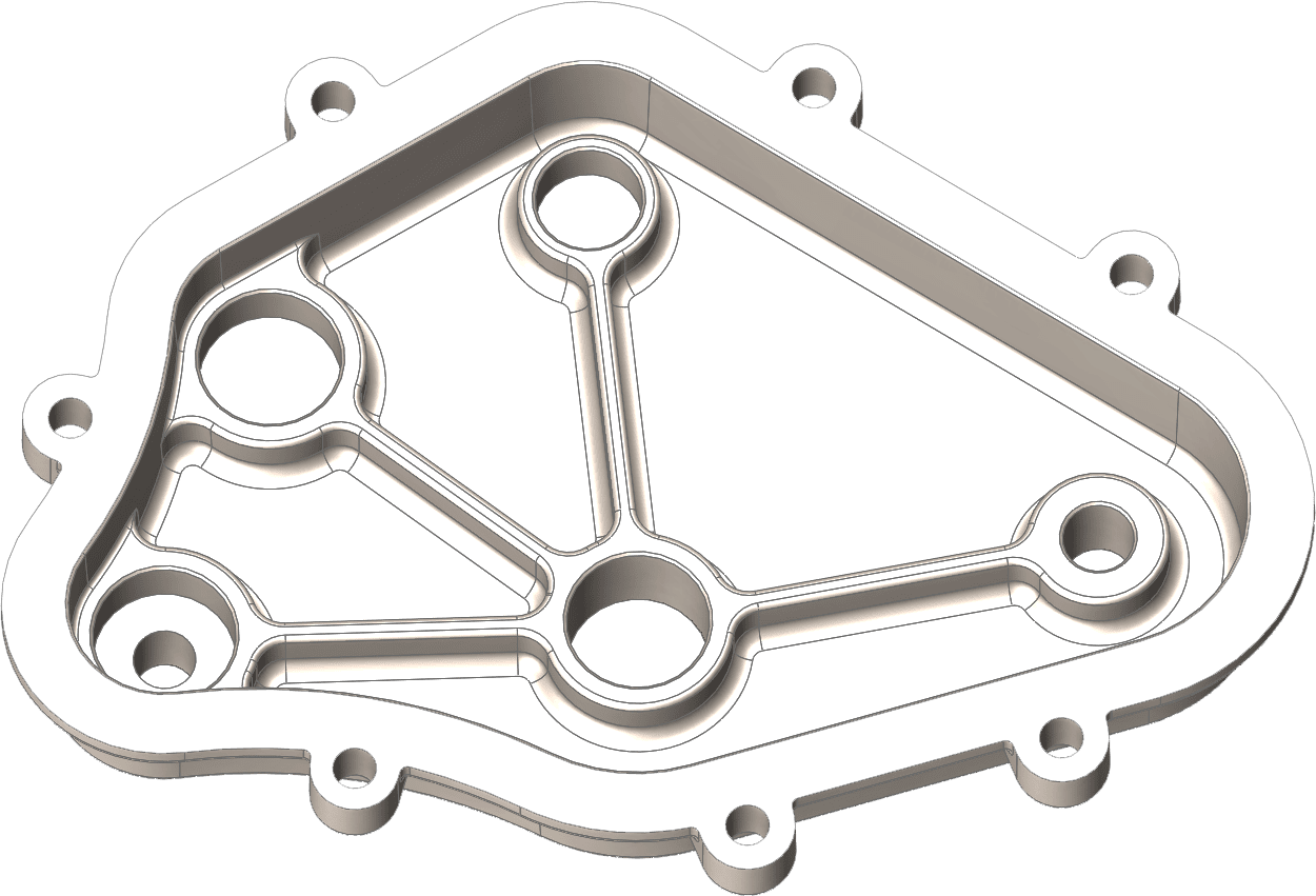
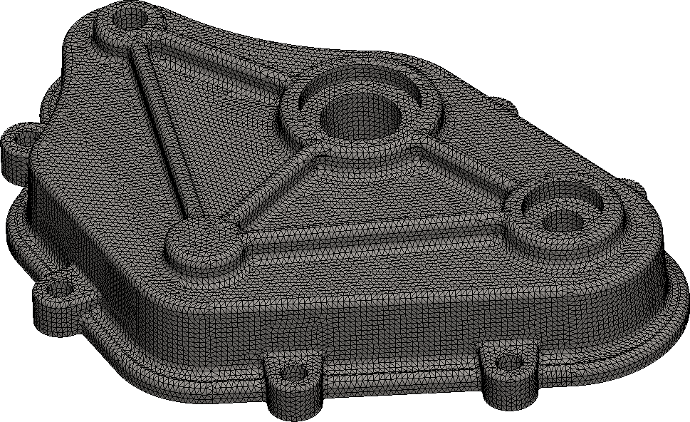
Let’s look at the case study we will use to explain this concept. The part is a cast cover. The cover is bolted to additional geometry. The cover is subjected to an internal pressure of 500 PSI. The cover has a series of bosses and ribs to help resist the internal pressure.
SOLIDWORKS Simulation offers three mesh parameter options, Standard, Curvature, and Blended Curvature. Each of these mesh options has it’s own strengths.
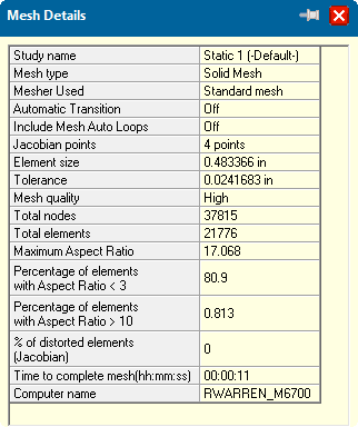
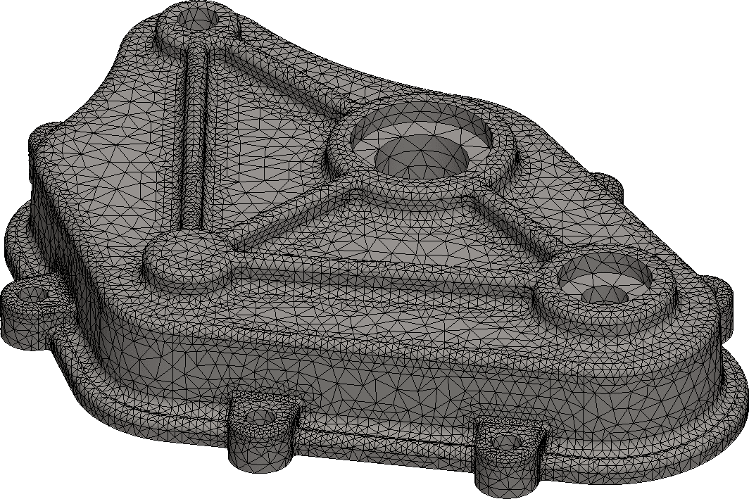
The Standard mesh option gives the user control over the global element size and tolerance. Simulation applies a mesh to the geometry keeping the cell size uniform throughout the model. This gives decent definition to the model keeping the overall Degrees of Freedom(DOF) low.
DOF in finite element analysis refers to how many partial differential equations the Solver is calculating simultaneously to generate a set of results for the user. This is usually directly proportional to solver time as well. Note DOF is the total number of nodes(where the calculations occur) multiplied by 3 translations(x,y,z). A 100,000 node model will calculate 300,000 DOF.
The cover meshed with the standard mesher generated a reasonable mesh with 38,000 nodes. Note the curved areas(ribs) of the case are fairly well defined with a couple of cells.
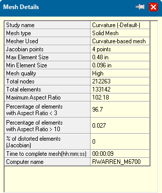
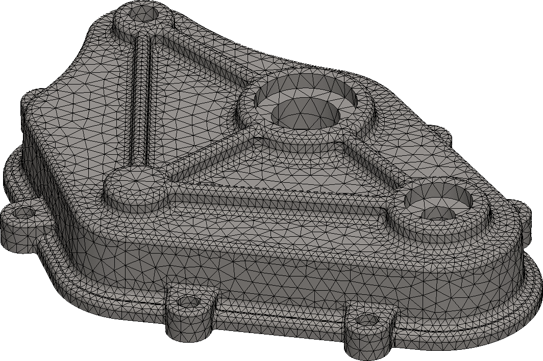
The Curvature mesh option automatically refines the mesh in areas of curvature in the model. The mesh becomes more dense in areas that the geometry transitions from flat to curved. The user specifies not only the global mesh size and tolerance, but the number of elements that define a cylinder, and the growth ratio(ratio that dictates how the mesh transitions from the global to the automatically refined size.
The Curvature based mesher using the same global size as the Standard significantly refined the mesh in all areas of curvature increasing the number of nodes to 212,000.
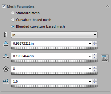
The Blended Curvature mesh options behaves similar to the Curvature mesh, however the Blended Curvature does its best to keep the Aspect Ratio(ratio or the cells longest side to the shortest side) as small as possible. High aspect ratio cells in areas of high stress can lead to bloated stress results.
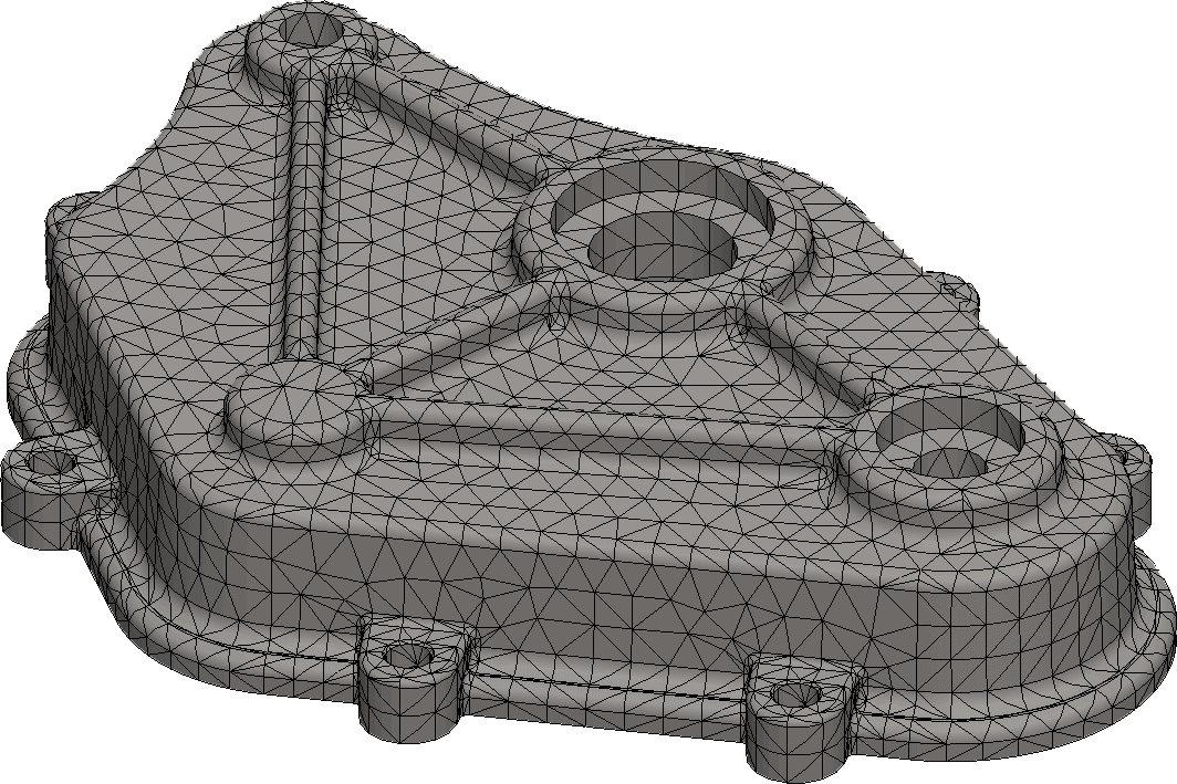
The Blended Curvature generated a node count between the Standard and Curvature with 97,000 nodes. The areas of curvature are well refined.
The Curvature and Blended Curvature reported the highest stress located in the ribs to be 54,000 psi(Curvature), and 53,000 psi(Blended). The Standard mesh reported a lower value of 42,000 psi. This is to be expected as the rib areas were not as refined as the two curvature models.
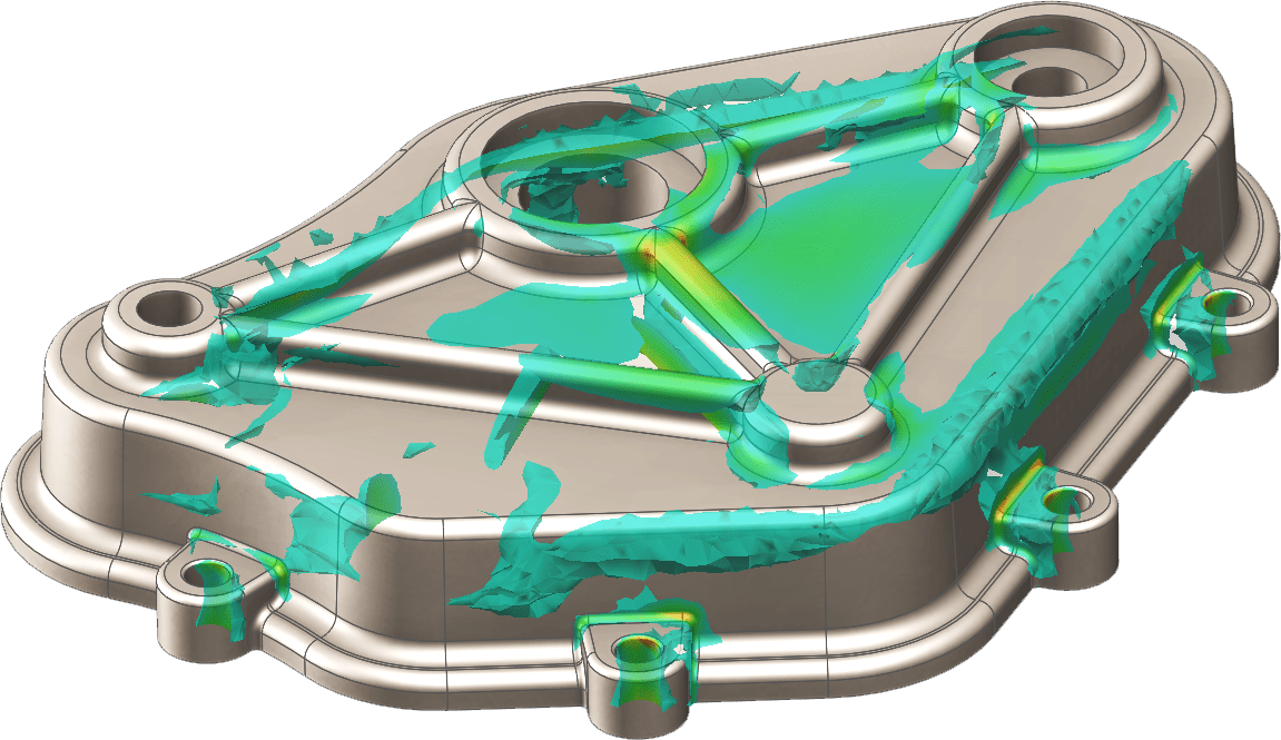
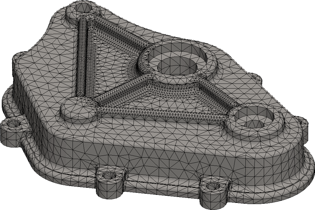
Knowing where the stress is located in the Standard model allows the user to apply mesh control to the areas in question. Mesh control can be applied to any mesh type, however when paired with the standard mesh option usually leads to lower DOF, converged results, and faster run times. Mesh control allows a user to refine the mesh about vertices, edges, faces, or bodies/parts. The default mesh control size is half the global mesh size but can be reduced as desired.
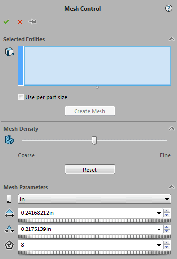
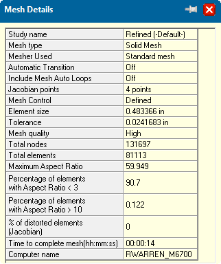
The standard mesh with mesh control added to only the ribs in question lead to 131,000 total nodes and a highest stress of 53,000 psi.
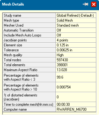
As a comparison an alternative method would be to globally refine the mesh without any local control. I would not recommend this as a global mesh reporting a stress of 53,00 psi resulted in 597,000 nodes, and a longer run time.
Based on the numbers above I would recommend two ways to take control of your mesh.
The first method is the tried and true old school way of using the Standard mesh. Utilize the Standard mesh to understand where the high stress areas are in the model. Apply mesh control to only the areas of high stress. Solve the newly refined mesh. Repeat the mesh control process reducing the element size as necessary(usually 4 times) to find convergence in the model.
The second method would be to use the Blended Curvature based mesh for the first pass solution. The Blended Curvature mesh delivers a good balance between refined areas and the number of DOF. This starts the user off at a closer value to the converged result. Mesh control is still required as a second step to verify convergence in the model.
No matter the mesh type you choose utilize mesh control to refine the mesh in specific high stress areas. This method helps reign in the bloating DOF a globally refined mesh leads to. Take control of your mesh and get results smarter, faster, and better.