Tight Fit Option with Bolt Connectors in SOLIDWORKS Simulation
How often do you utilize a bolt connector in your analysis work? Have you ever investigated the multitude of options available with this virtual connection? If you have, how many of the options were intuitive? In a prior blog, I wrote about the bolt series option to fasten more than two components. In that article, I truncated the bottom portion of the Advanced Options section of the bolt connector property manager. The full Advanced Options section is shown in Figure 1.
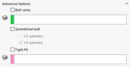
Figure 1. Bolt Connector Advanced Options
There are five types of bolt connectors available in SOLIDWORKS Simulation. They can be utilized to fasten multiple components together or for connecting a single component to ground. To advance your knowledge of bolt connectors, spend time digging through the Help files starting here. I am going to detail what the Tight Fit option means and demonstrate how it can affect your analysis results.
The big picture description of the Tight Fit option can be associated with machining tolerances. If you are not familiar with limits and fits, that is an entirely different topic that I encourage you to research. You may have looked at an engineering drawing and noticed alpha-numeric callouts next to dimensions, like H7 or g6. These designations provide machinists with the tolerances allowed for features they will be machining. You can think of the default bolt connector setting as a clearance fit. Alternately, if you utilize the tight fit option, this can be thought of as using a transition fit. An interference fit would be better associated with a shrink fit interaction in SOLIDWORKS Simulation.
My SOLIDWORKS CAD model consists of two Alloy Steel plates, each 150 mm long and 60 mm wide. They are fastened together using two M8 x 1.25 hex head bolts and hex flange nuts. The bottom plate in Figure 2 has a fixed restraint on the end away from the bolts. The top plate has a 2000 N load applied in the positive-X direction (towards the lower right corner in Figure 2). There is a local contact interaction defined between the coincident surfaces between the two plates. To reduce solve time, I am going to solve half the model using symmetry along the mid-plane of the bolted assembly. The lone smart fastener was converted to a bolt connector using the Automatic Conversion of Toolbox Fasteners option when setting up the study.
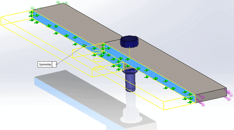
Figure 2. Half-symmetric model with Bolt Connector
The first finite element model was solved using the default option for a bolt connector, i.e., Tight Fit not selected. If the geometry of the bolt and flange nut were included in the model, there would be clearance between the bolt shank and the ID of the thru holes. To understand how this virtual clearance affects the analysis, an X-displacement plot showing only results on the thru-hole faces is appropriate (Figure 3). This shows a maximum translation in the x-direction of 0.07 mm around the top of the thru-hole, which virtually represents the translation of the top plate until contact between the bolt shank and thru hole develop.
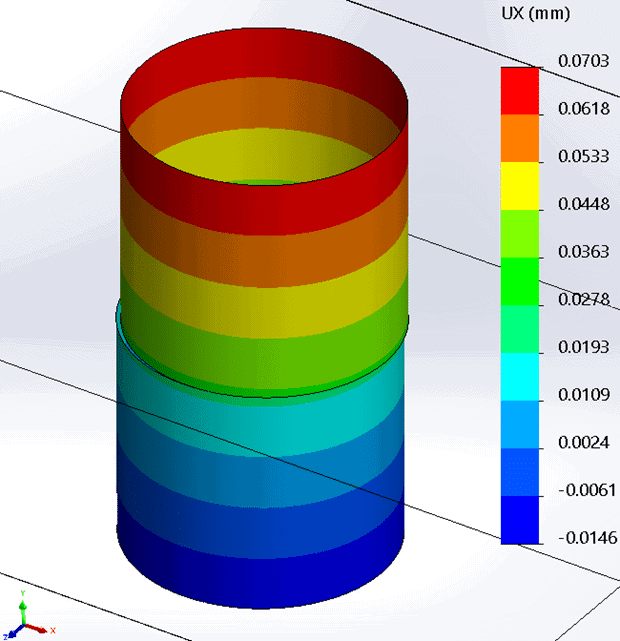
Figure 3. Ux displacement result of a normal fit bolt connector
Creating a Pin/Bolt check plot of the bolt connector for this finite element model (Figure 4) provides additional insight into the forces the bolt connector experiences and calculates a Factor of Safety for the bolt.
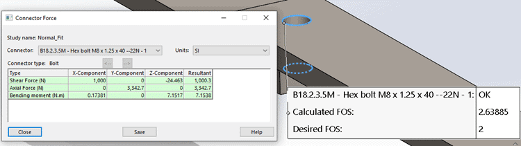
Figure 4. Normal fit bolt connector check plot results
To investigate the Tight Fit option, I duplicated the Normal Fit study and modified the bolt connector definition. When editing the connector, expand the Advanced Options section of the property manager, check the box for Tight Fit, then select the ID faces of both thru holes from the graphics window (Figure 5).
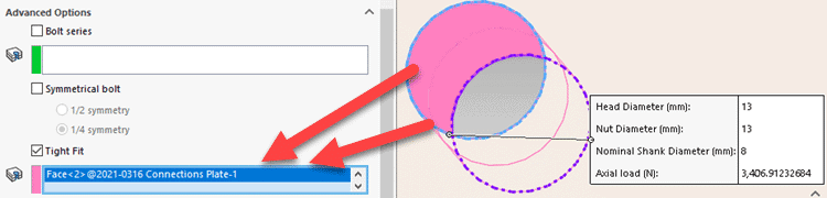
Figure 5. Setup for Tight Fit option
This change will require the finite element model to be re-meshed with the modifications to the connector definition. After solving the finite element study, the x-displacement result changed (Figure 6). The maximum x-displacement has been reduced to 0.06 mm, which is roughly a 13% reduction. The Tight Fit option represents that there is not clearance between the bolt shank and thru holes at the start of the analysis. The physical geometry would already be in a contacting position prior to the tensile load being applied to the bolted assembly.
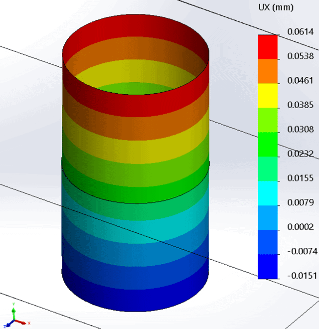
Figure 6. Ux displacement result of a tight fit bolt connector
To complete the investigation into the Tight Fit option, I re-visited the Pin/Bolt Check Plot for the bolt connector. The results are shown in Figure 7. The calculated Factor of Safety increased from 2.64 to 3.58 for the virtual bolt. The shear force is identical between the two studies, however, the bending moment that the bolt connector experiences in the Tight Fit study is reduced by almost half.
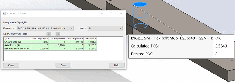
Figure 7. Tight fit bolt connector check plot results
Just as I wrote in the Bolt Sandwich blog, the next time you need to solve a bolted connection in your finite element model, I hope you spend some time with your fastener setup to make certain it will solve correctly. Just as I demonstrated in my example model, how you set up bolt connectors for your analysis work will affect your results. Now go make your products better with SOLIDWORKS Simulation!
Bill Reuss
Product Specialist, Simulation
Computer Aided Technology, Inc.