Topology: How to Use Results as a Design Guideline
Topology optimization in SOLIDWORKS Simulation allows users to make lightweight, strong components. However, the resultant shape is often too complex to manufacture or contains sharp geometry. How do we take the data from Topology optimization studies and make something useful? I have designed an odd looking bracket that we can use to demonstrate a couple techniques. Fair warning, nothing you are about to see will blow you away, but you just might find a few tips to make things easier. Also, the scope of this blog does not include the process to setup a Topology study.
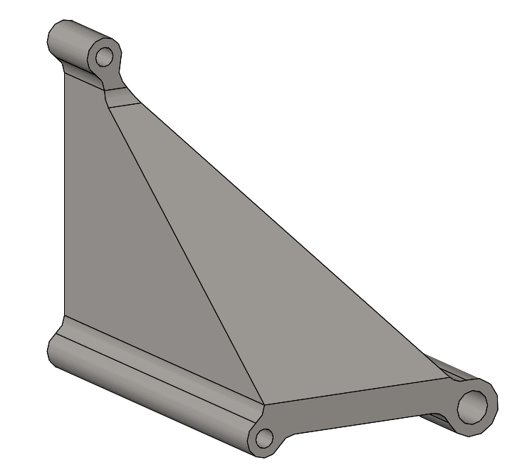
Above you see the design for a strong bracket that gets the job done. The drawback, this bracket is heavy. A Topology study sacrifices strength for weight. The amount of strength sacrificed is determined by goals generated by the designer. Upon completing the setup and running the study, we may get a result like the yellow body picture below.
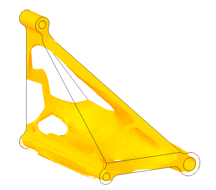
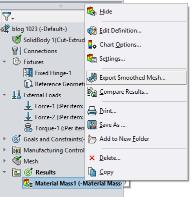
This body contains too many intricacies in its current state to cheaply manufacture in a CNC mill. Of course we could print this part, but its made of metal. Metal 3D Printed parts do not currently have the same strength as milled parts. Why don’t we use the yellow part as a template to model our own geometry? We accomplish this by saving the yellow meshed body into a new part using the Export Smooth Mesh functionality.
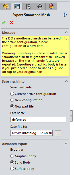
Once in the command we have options to save as a new part and choose to export as a solid, surface, or graphics body.
Then insert the deformed body into the original bracket part (this is called a derived part) using the Insert Part function.
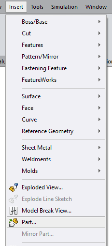
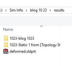
By default the deformed part is found in the results folder for your simulations. The results folder is found in the same directory as your part at the same location as your part file.
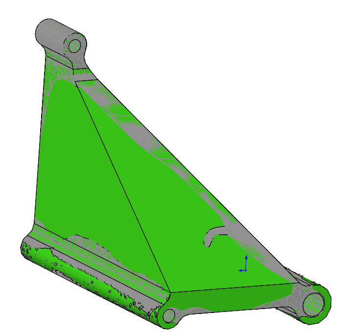
The parts will look odd because they are partially sharing the same surface. Use sketches to follow the same of the deformed body and cut away the material. Shown below the deformed superimposed on the body with cuts.
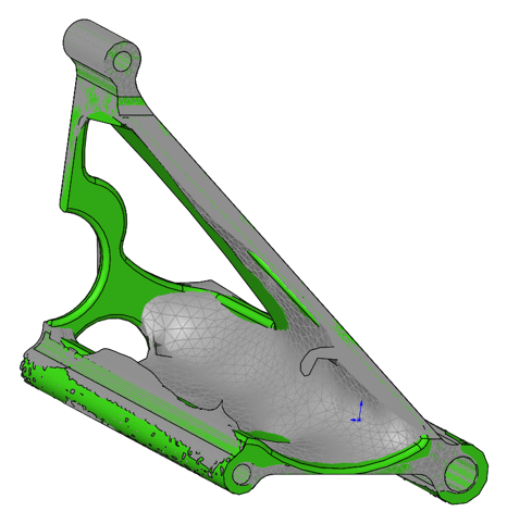
And here is the bracket by itself with the cuts and fillets.
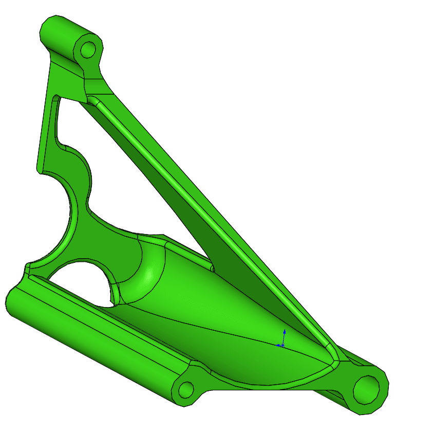
I have followed the Topology optimization result as close as I could for comparison’s sake. Keep in mind this is only a guide so feel free to deviate from the exact shapes you find in the Topology study. Once this is done, run a static study on the part to ensure it won’t fail.
Thank you,
Matthew Fetke
Application Engineer, Simulation
Computer Aided Technology, LLC