Understanding Pretty Pictures!
Interpreting results helps users understand product
behavior. “Blue is good, red is bad” is
the general adage. While this might hold true in some cases, it is wrong to
generalize. As appeasing as color plots may seem, interpreting them could be
tricky.
Animate….it’s cool!
Animations are the best way to understand part or model
behavior. If the part or assembly does not move as expected, users need to go
back and change the set up. This very basic method should eliminate the majority
of set up mistakes. Animations also help with communicating with team members, and
marketing in-house engineering capabilities on the company website.
Displacement
This indicates how much and in what direction the part moves
under an applied load. If the values seem plausible, it is worth exploring the results
ahead.
Failure
Whether a component will hold or fail under an applied load
depends on how it interacts with the applied load. This is determined by a
parameter called stress.
Stress
Stress is the internal reaction generated by a component to
an applied load. Therefore, stress is not a material property. Meaning, stress
does not depend on whether a component is made of steel, plastic or rubber. Stress
can be classified into 3 broad categories.
- Normal Stress occurs normal to the face on which a load is acting.
- Shear Stress occurs when the top and bottom of a material are pushed in opposite horizontal directions.
- Principle Stress occurs on a plane internal to a component where shear stress is zero.
When to use what? This depends upon the loading scenario.
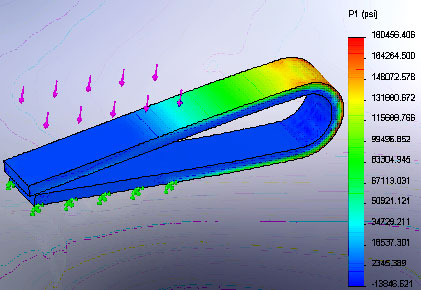
- First Principle Stress (P1) is the maximum
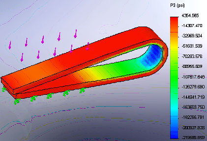
stress under tensile loading, i.e. if components are being pulled apart. - Third Principle Stress (P3) is the maximum
stress under a compressive load.
Principle stress works as a failure criteria with
brittle materials like cast iron, etc.
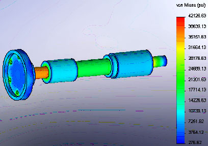
- Von Mises Stress is the overall state of stress in a component under an applied load. This combines the effect of normal and shear stresses in a component. Von Mises Stress works as a failure criteria for ductile materials like steel, aluminum, etc.
Yield Strength
Yield is the maximum load a component takes before
deforming. Usually any deformation is considered as failure.
Ultimate Strength
Ultimate strength is the maximum load a component takes
before failure.
Factor of Safety
(F.O.S)
Factor of Safety is defined by failure mechanism for a type
of loading. It is calculated as a ratio of Yield Strength to failure criteria for a component. The
failure criteria can be Normal stress, Shear stress, Von Mises Stress or
Principle Stress depending upon load type and material used.
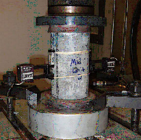
Co- relating Analysis
to Test data
If you are measuring the response of a structure using strain gages
make sure they are mounted at locations where stress varies gradually.
Also, the direction in which strain gage is mounted plays a big role.
While setting boundary conditions, make sure the physics in the
model is considered. If material properties are changing with temperature or
load scenario, make sure to model that into the simulation.
Also, make sure to model part interaction in assembly
environment. If parts are lubricated to smooth the movement make sure to model
that with the appropriate friction factor in simulation.
Rajat Trehan
Product Manager – Design Validation
Computer Aided Technology Inc.