SOLIDWORKS Lip and Groove Brings Parts Together
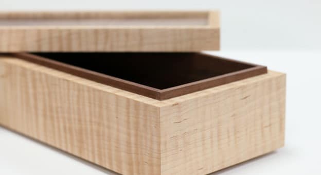
I was dragged out to an antique mall recently, and to quench my boredom, as we designers often do, I was imagining how exactly I would model things that I happened upon. As I was turning an old jewelry box over in my hands, I noticed a lip and groove that ensured that the lid stayed snug on the base.
Much like this one:
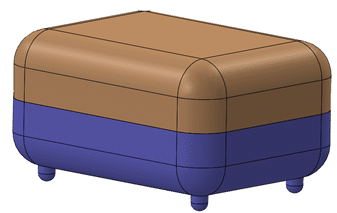
I got to thinking about the modeling of this box…
Making the lip and groove in a model sounds like it should be a cinch, the inside of the lid just needs to be as wide as the outside of the lip. Well, that’s all fine but making those dimensions manually means that they are not going to change very easily with the rest of the model, and what if I need a little bit of space between the lip and groove for padding, or draft so they mate together nicely? You can see how this design can get tricky very quickly. Thankfully I realized that SOLIDWORKS can do all the work for me when making a lid seat like this with a LIP AND GROOVE feature, part of the fastening features available in SOLIDWORKS.
Lip and Groove features work like this:
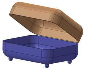
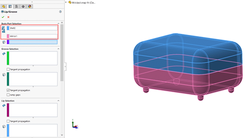
- Start with a multibody part or assembly with the body faces you would like to make the lip and groove on, lying flat against each other. (In the second image, I moved the lid for clarity)
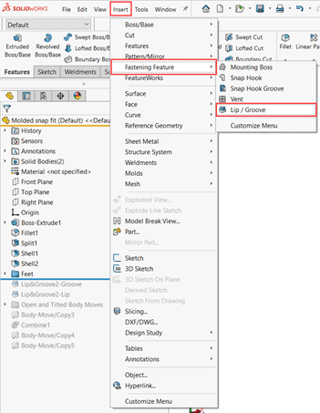
2. Insert>Fastening Feature>Lip / Groove
3. Choose the bodies for which you want the groove and lip on in the blue and pink selection boxes, respectively
4. Now choose the face and edge that you want the groove to appear on (in this case it will be the flat mating face of the lid and the inside edges of that face). SOLIDWORKS will hide the other bodies to make your selection easier.
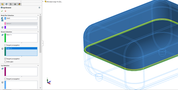
5. Repeat Step 4 for the Lip Selection
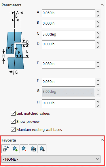
6. Set sizing for the lip and groove in the Parameters section of the feature manager
7. Save as favorite if it is a commonly used sizing!
Once you accept the lip and groove feature, you should see something like this:
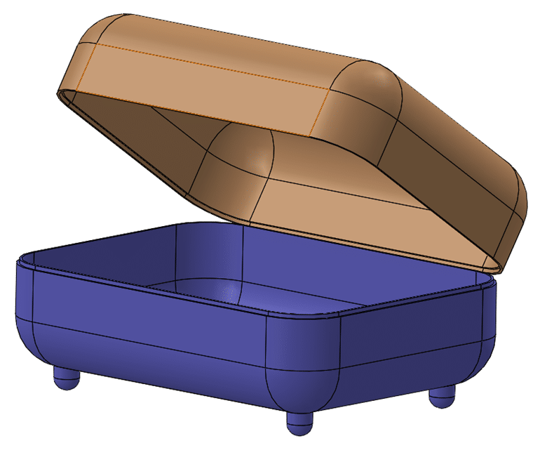

This is a huge time saver as an alternative to modeling this feature manually. This tool and the other fastening features are especially helpful for designing plastic parts. With a few extra features, you could have a snap fit in… well… a snap!
I hope this helps you shave some time and effort off your daily designs.
Happy modeling!
Kit MacDonald
Application Engineer
Computer Aided Technology