How to Include Character Zone Information in SOLIDWORKS Inspection Standalone
When dealing with drawings that have an excessive amount of ballooned characteristics and there is no logical order in which the balloons have been placed, it can become very difficult to locate the dimension on the drawing. At times, it can even be difficult if it is a clockwise or counterclockwise progression of the balloons. SOLIDWORKS Inspection allows the user to place grid lines on the drawing so that the balloons can be found quickly.
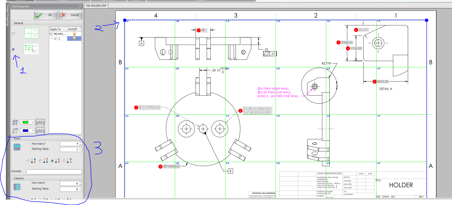
Once you have ballooned your drawing, go to the Drawing toolbar and select Grid. This will take you to another window where you can specify how you want the grid to be laid out on the pdf.

The first thing you want to do is reduce the grid extents so they match the border of the drawing. This means, click the second bullet point in "step 1" of the image. Then drag the blue balls at the corner of the drawing inward, pointed out in "step2." Once you get that approximately right, adjust the number or rows and columns to match your drawing which is "step3."

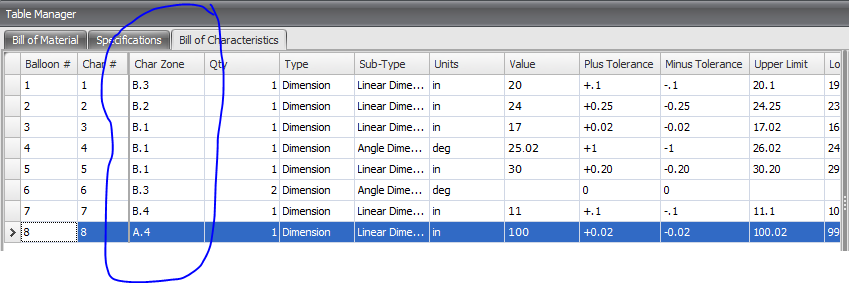
Once you hit the "OK", you will see the Char Zone in the Table Manager filled out. Those values can then be extracted to your FAI report.

Thanks
Ketul Patel
Computer Aided Technology

 Blog
Blog