SOLIDWORKS: Making Sense of Simulation Meshing - Part 1
Making Sense of SOLIDWORKS Simulation Meshing – Part 1
As an Application Engineer specializing in SOLIDWORKS Simulation, I often get asked, “How do I know if I have a good mesh?” The simple answer is, it’s not so simple. This is the first blog in a 3 part series that I will be posting about meshing. In this blog we will discuss meshing considerations for study types and purposes as well as mesh convergence considerations. The next two blogs in the series will talk discuss mesh quality tools, what they mean, and the types of meshers.
Meshing is a term for the process of discretizing CAD geometry. For the purpose of this blog series, we will only discuss solid elements. In terms of SOLIDWORKS I often solid elements to building your CAD model out of Pyramid shaped Legos. Mesh density is perhaps the biggest factor in solution time. A mesh with many elements or “dense mesh” will usually yield a closer to real life solution, but it has many more degrees of freedom and therefore will take much longer to solve. On the other hand, a mesh with fewer elements will not take as long but may not yield as realistic of results.
Below are some of the more important factors for mesh size considerations:
Type of Study
Some types of studies have much more need for a finer mesh than others. For example, typically frequency studies are not as reliant on a fine mesh as a stress based FEA. As a basic rule, the more advanced the study, the finer the mesh should be. Studies like nonlinear with complex sliding contacts will require a more dense mesh than a basic static cantilever beam. Any time there are large displacements in a study, typically more elements in the mesh allows for a better capture of the behavior.
What are you looking for?
Anyone who has used any simulation software can attest to this. CAD model comes in, with the question, “can you simulate this?” Without any background or expectations from the model, simulation is useless. It is important to know which results are important to the study. Do you only care about deflection? If so a coarse mesh will probably do just fine. Are you more concerned about stresses around small features? A finer mesh may be better. If you only need the mesh to transfer a load to another part, then more coarse mesh will suffice. Simplify the study as much as possible and make sure to understand the results you are expecting. Use discretion to judge if the extra time needed to run a finer mesh study is worth the small increase in target accuracy.
The Nitty Gritty
Another problem that can lead to difficult meshes is small features. If the CAD model has small holes, fillets, embossed/ debossed text, then the mesher may use these small features to drive the global mesh size to a value that is smaller than necessary. In cases with small geometries like these, it is best to defeature the part and remove small features that do not contribute to the overall stiffness of the model or the loading path.
So, What do I Do?
This may be a lot to keep in mind, so you may be thinking, how can SOLIDWORKS help me make sense of all of this? Luckily, as with most things, SOLIDWORKS has tools that make your job just a bit easier. For meshing in particular, there are a few tools that may be useful to overcome the issues listed above.
Convergence Studies: In Simulation, the best indication that results are realistic is accomplished through changing the size of the mesh and monitoring the effect on the results. This process is known as mesh convergence. If the results don’t change very much from one study to another with a finer mesh, the results are considered converged. This process can be very manual and depending on the size of the model, take a very long time. Included in SOLIDWORKS Static Simulation are the h-adaptive and p-adaptive meshes (Found by right clicking the Study Name-> Properties-> Adaptive tab).
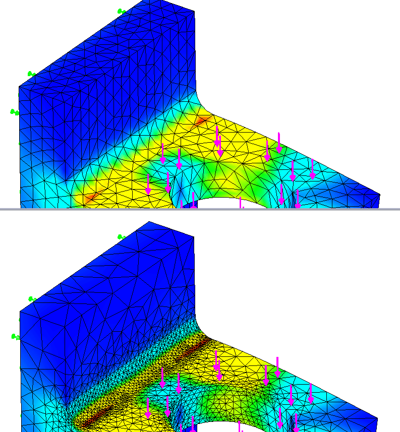
H adaptive: The solver and the mesher will run in loops; changing the size of the mesh over every loop until a specified tolerance is achieved. H adaptive meshing makes elements smaller in areas of high stress, and has the capability to make them larger in areas of lower stress. The picture below shows a default mesh on the top and an H-Adaptive on the bottom. Notice the smaller elements in the high stress areas and bigger elements in the lower stress areas.
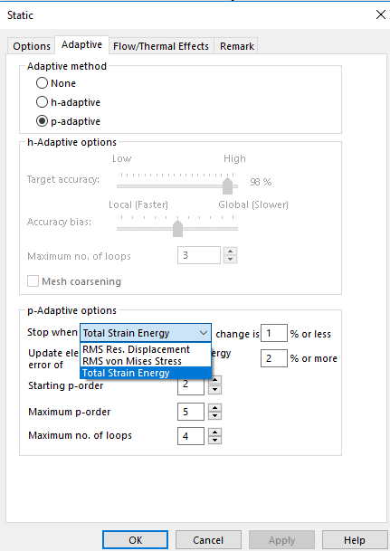
P Adaptive: The p adaptive study does not change the mesh topology. Instead, the P adaptive study changes the polynomial order of the element. For example, a 1st order element can only deform linearly (y=x). P adaptive lets the elements deform up to the 5th order (y=x^5). P Adative studies allow for 3 different criteria for convergence seen below.
For more information regarding convergence please refer to SOLIDWORKS help or your local simulation applications engineer. Stay tuned for the next part in the mesh series where we will discuss mesh quality tools!
Thank You,
Matt Sherak
Simulation Application Engineer
Computer Aided Technology