Stratasys 3D Printing: Wiper Position Adjustment Objet Desktop Printers
Wiper Position Adjustment in Stratasys Objet Desktop Printers
In Stratasys 3D Printing, the wiper position adjustment sets the wiper service position and the wipe position.
This procedure should be performed whenever the wiper mechanism is replaced. It does not need to be performed when the wiper blade is replaced.
To do this procedure, you will need to be in Maintenance Mode. To get into Maintenance mode, move the mouse cursor to the bottom right corner of the screen until the cursor disappears.
With the cursor just barely off the screen, press CTL+ALT+M keys at the same time. You should see a warning box pop up:
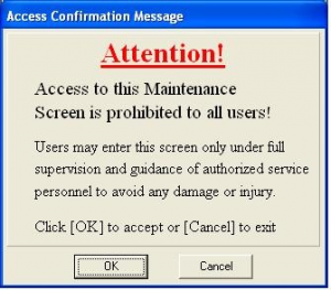
When you see this box pop up just press the enter key.
You should now see File Options Maintenance and Help at the top of the printer software screen. Click on Maintenance then click on Motors Control.
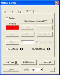
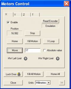
Click on the T tab.
Click Go To Service Position (X,Y.T).
When the T Axis stops moving an error message may appear.
Do not worry about this error message just Click on OK.
Click Save Service Position.
Carefully adjust the wiper waste collector height by typing in a value in the box next to the move button and then click the Move button until the wiper blade is 2 mm below the orifice plates of print heads (see pictures below).
1 mm of movement of the wiper position is 5486 steps.
To avoid damaging the print heads, make sure they stay above the metal parts of the wiper waste collector.
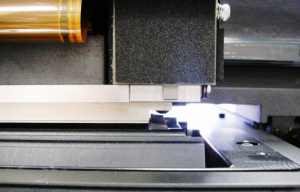
Adjust the position of the print block along the X-axis and the Y-axis by clicking on the X and Y tabs at the top of the motors control screen and then type in a value of 10 steps or less in the box next to the move button then click the Move button until the print heads are aligned with the rubber wiper blade.
The wiper blade (when viewed from the front) should be below and centered under the print heads.
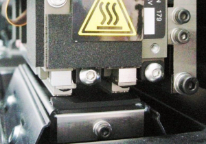
The wiper blade position (when viewed from the side) should be 2–3 mm under the front edge of the print heads.
In the printer application, select Maintenance then Parameter Manager
From the parameter manager list, select Purge. The Purge parameters appear.
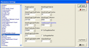
Select the X tab and copy the value from the Position field into the MotorsPurgeXStartPosition parameter. Before you copy the value from the Position field, make sure the unit of measurement is in millimeters.
Click Apply then Close.
Select the Y-tab and copy the value from the Position field
into the MotorsPurgeYStartPosition parameter.
Click Apply then Close.
Select the Y tab of the Motors Control screen.
Move the heads forward by typing in a value and then clicking move until the heads are above the wiper blade.
Carefully adjust the wiper waste collector height by clicking on the T tab and typing in a value and click move until the wiper blade just touches the orifice plates of print heads.
Move the wiper up 0.35 mm (1947 steps).
Click Save Wipe Pos.
To test the adjustments, Click on Options-Execute Purge Sequence and then click Yes to confirm.
Watch the wiper to verify it moves correctly in to position and properly cleans the heads then go back to the motors control screen and click on the z tab then click on Go Z down. Place the mirror on the tray.
Move the print block over the mirror and verify the heads are clean.
Remember to remove the mirror.
Click Home all.
Paula Durham
Computer Aided Technology