Working With Mesh Files - Outside The Box 3D Prints
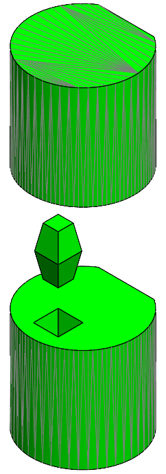
The Hybrid Modeling enhancements in SOLIDWORKS 2022 brought new quality of life benefits to users working with mesh files. We no longer need to convert each body into a mesh body for feature creation because of the simplified workflow. We do need to account for build volume and the geometry of the file. These factors determine which 3D Printer it will be printed on. When the limiting factor is build volume we split the model or file into multiple pieces. This brings another challenge – aligning the pieces during the bonding process.
This is where hybrid modeling comes into play. I can take the mesh file and open it in SOLIDWORKS, then split it into pieces that fit in the build volume of my 3D Printer. Then I can add features that aid in positioning and locating the parts during the bonding process. You can get creative with how you do this. I will go over a simple example you can apply to your designs or use as a springboard for brainstorming new methods.
Working with Mesh Files in SOLIDWORKS
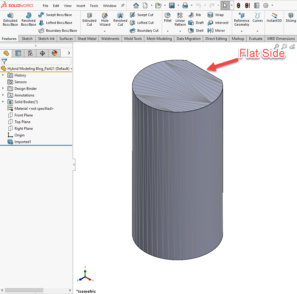
Now I want you to look at the model shown below and pretend that it is much longer than shown and that we need to split it up in order to fit it in our build volume. I am using a shorter model in this example to 3D print it faster and not waste material. If you look at the model, you will see that it is essentially a cylinder with a flat surface on one side. This means there is a possibility that the parts could be bonded incorrectly together, and the risk of misalignment has increased. I will mitigate this risk by adding a feature that will aid in positioning and alignment between the bodies.
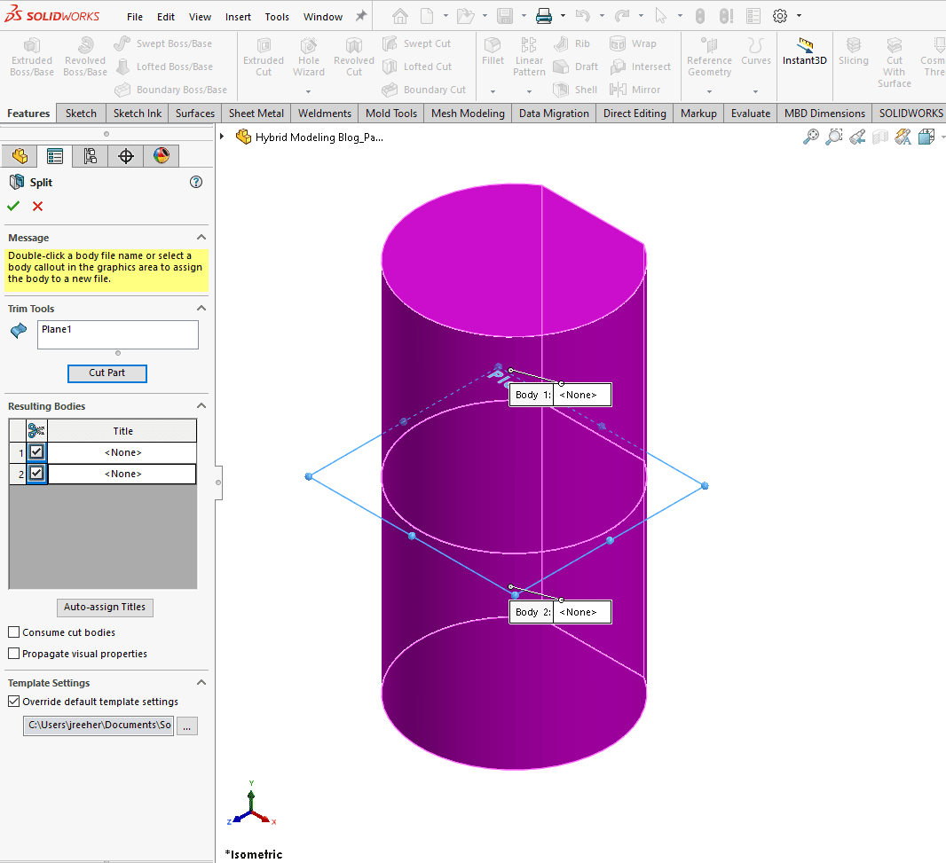
I will start by adding a plane and performing a simple split of the part.
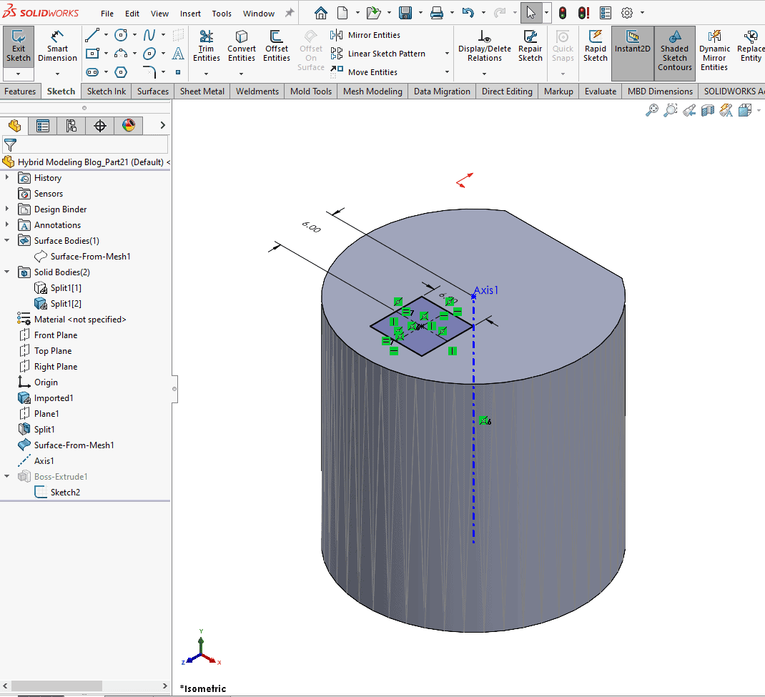
Now I will hide the upper body and sketch a square on the top surface of the lower body.
I will then extrude this sketch and turn on the draft for this feature, making sure to uncheck the merge result option.
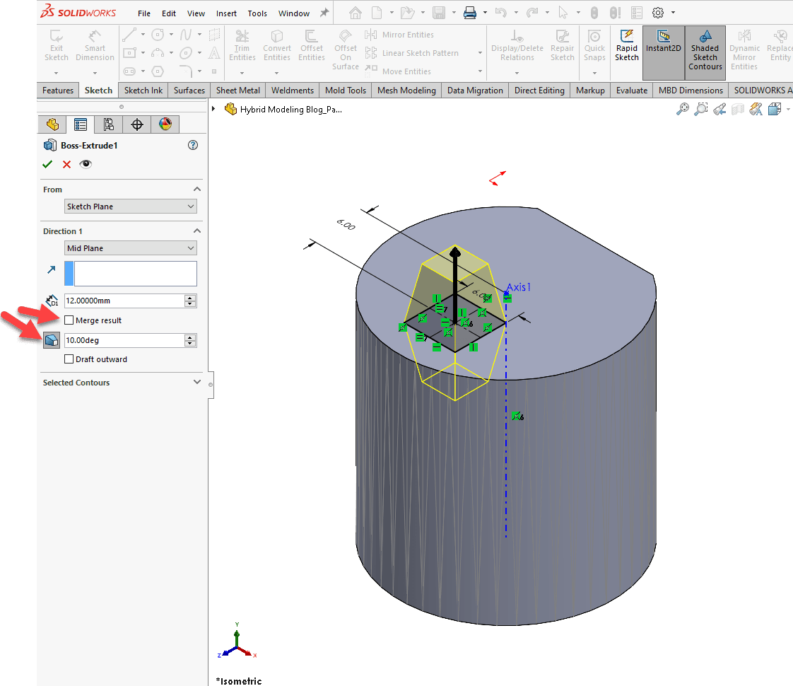
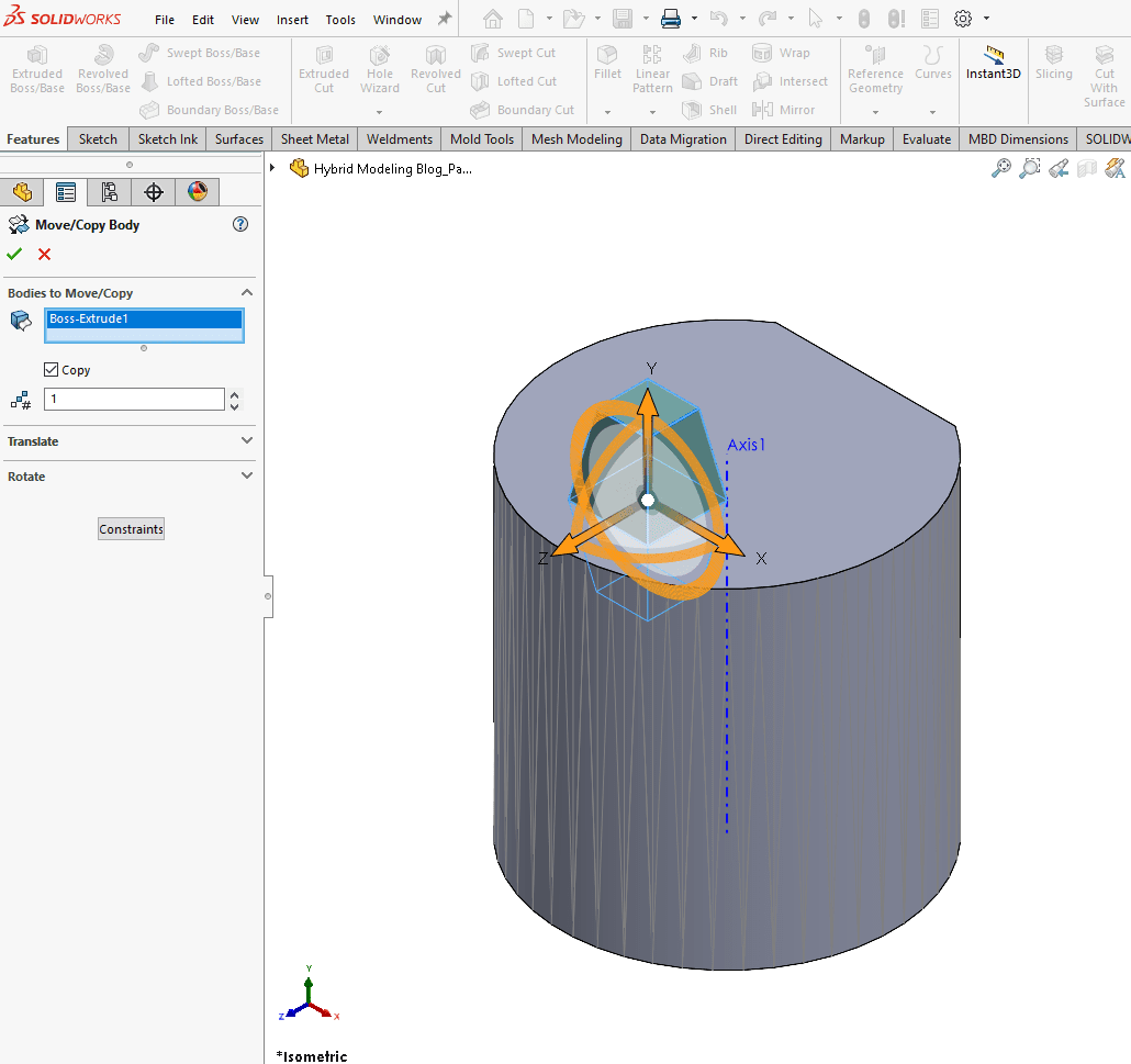
I then copy the body (Move/Copy Body command) and perform the Combine command to subtract that body from one of the other bodies. We use the direct editing tools in SOLIDWORKS to make working with mesh files significantly easier.
Below shows the copy body command.
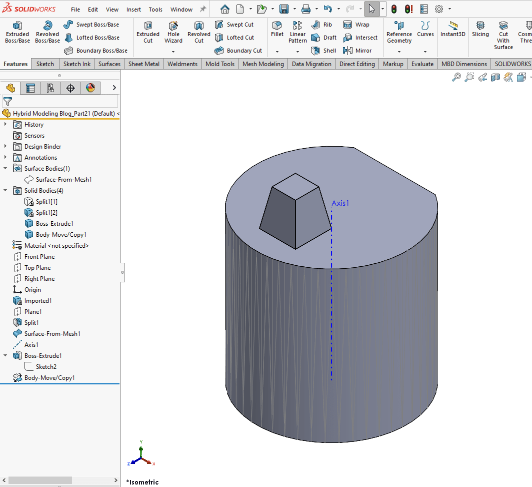
The copied body is shown in FeatureManager Design Tree below
Next, we see our combine command.
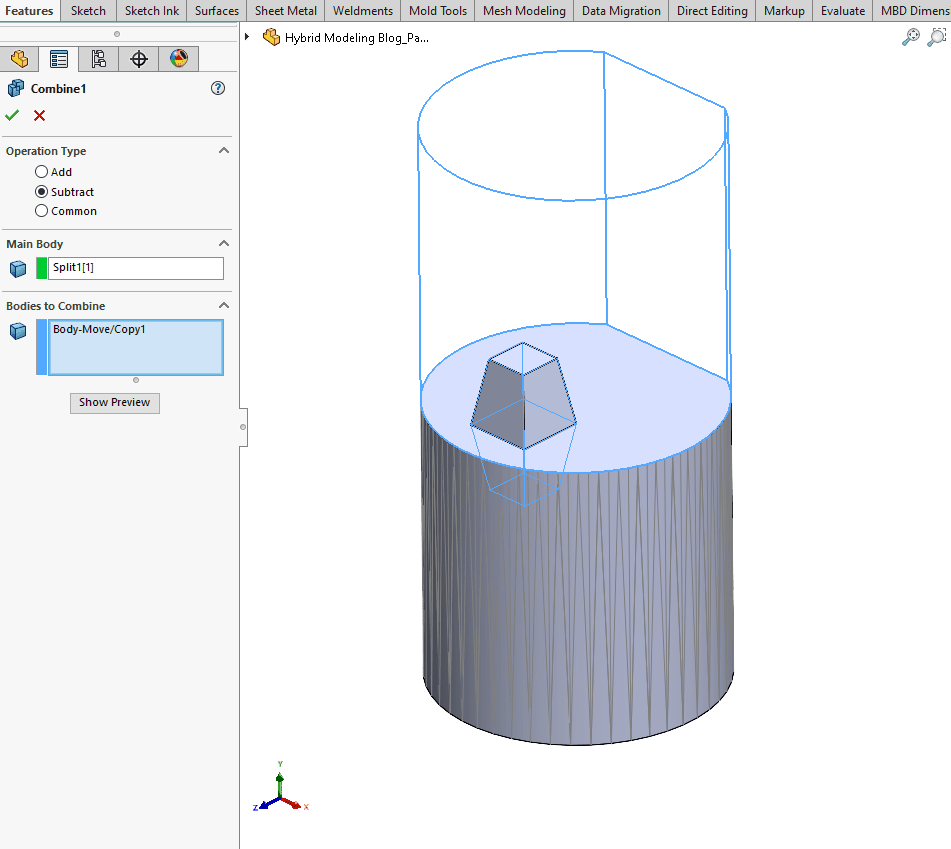
We’ve subtracted material from the lower body by using the combine command. See the image below.
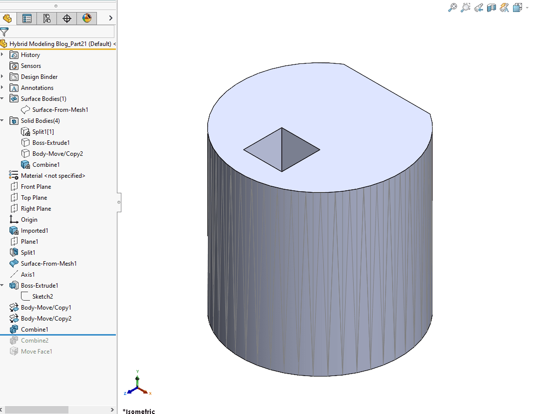
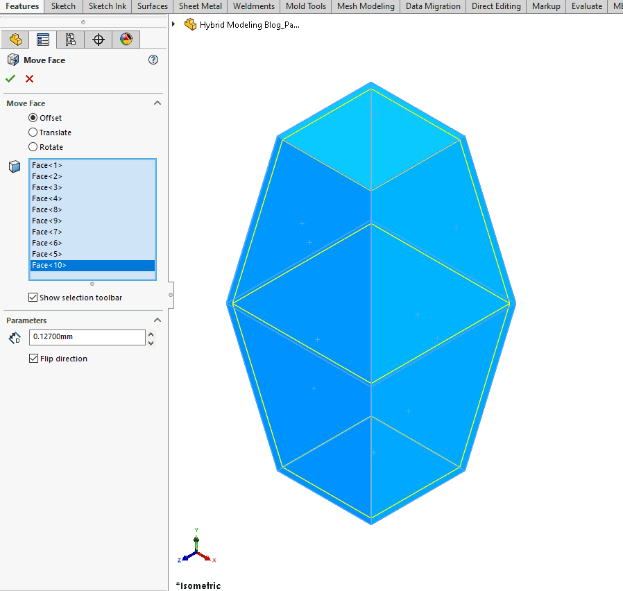
I then repeat this process as many times as necessary. In this example, I used Move/Copy Bodies twice and Combine twice. Next, I used the move face command to apply a small offset distance on the remaining Boss Extrude feature (Locating Feature). I applied it so that it moved all of the faces in a little bit. Different 3D printers have varying holding tolerances, making this an important step. Generally, an offset distance between 0.005in(0.127mm) to 0.002in(0.0508mm) is a good starting point. We need to account for the adhesive we’re using, so this helps with accounting for it. Adjust the value as necessary for your equipment.
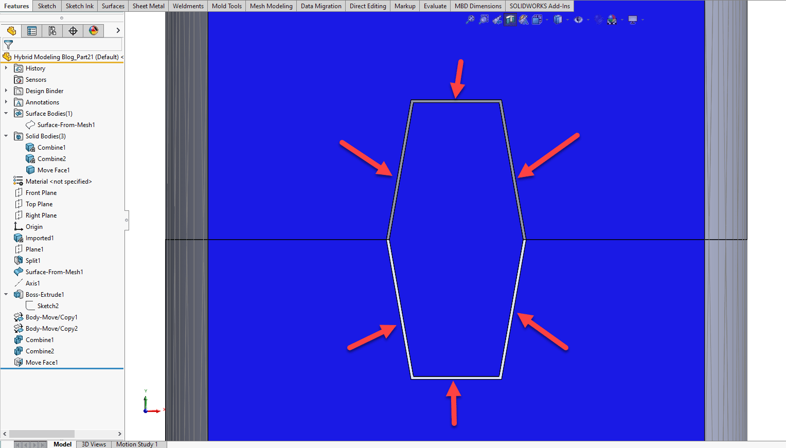
Below is a sectional view to show the gap between the faces of the locating body and the top and bottom bodies.
Here, we have pictures of the final build!
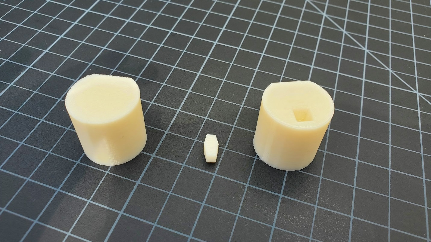
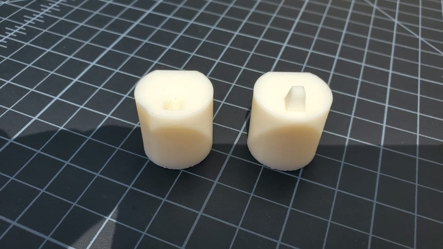
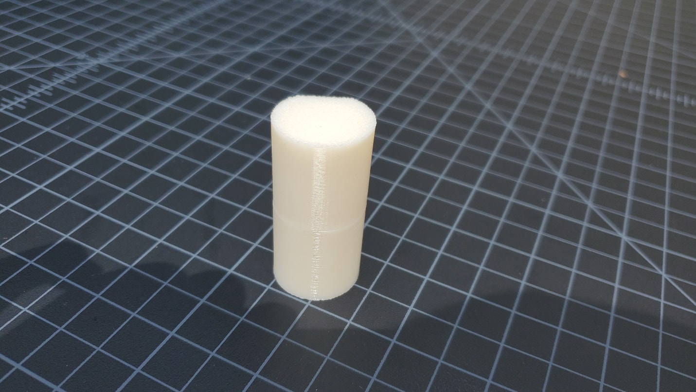
Now you can make all the “Lord of the Rings” cosplay props that you want! Don’t let build volume hold you back!
James Reeher
Sr. Application Engineer
Computer Aided Technology

 Blog
Blog