Managing Part Curl in Your FDM Parts
Have you ever gone to pull your part out of your FDM 3D printer and come to find that a corner or a portion of the part has curled off of the build sheet? Well I know I have, and not only is it frustrating but it can also affect the function and/or appearance of the part.
In today’s blog if you use the Insight program from Stratasys to process your STL files I want to walk you through a simple tool that helps to prevent that curling problem.
There are a couple tools in Insight that help to prevent curling from occurring but one of the tools, I find most effective, is Anchor Columns. How do Anchor Columns work? Normally, support material is applied between the build sheet and the part in order to make it easy to remove the part from the build sheet. This tool produces a thin, two linked contours thick, round column of model material that is built directly onto the build sheet and interfaces with the first model layer of your part.
Support material will still be built between the model and the build sheet, however the support material will build around the columns giving you a direct anchor between the part and the build sheet. This Anchor Column tool will help to prevent your part from curling off of the build sheet.
To apply anchor columns to your part follow these steps: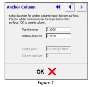
Go to the “Support” menu and select “Anchor column”. (See Figure 1)
Determine the Top Diameter and Bottom Diameter of your anchor column.
Tip: Using a smaller top diameter will minimize any witness marks when the anchors are removed from the part.
Go to the bottom layer of the part location where the anchor will be applied. Change to a top-down view.
Place your mouse cursor in the approximate area where you want the center of the anchor column and press the left mouse button to locate the anchor. (If it doesn’t land right where you want it, move your mouse cursor and press the left mouse again to locate the anchor. The anchor is not permanently placed until you press ok in the Anchor Column menu. (See Figure 2)
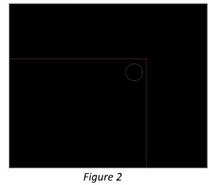
Press the OK button in the Anchor Column menu to confirm the location of the anchor column.
Repeat these steps to place additional anchor columns. (All anchors columns need to be placed and confirmed before generating support material.)
Once all anchor columns are placed and confirmed generate support material and run tool paths. Page down through the layers to verify that the anchor column has been placed. (Notice that the support material will be generated around the anchor column.) (See Figure 3)
After the part is printed and support material is removed I like to use a sharp 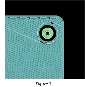 chisel to break the anchor column off as clean as possible and go back with sandpaper to smooth the area.
And there you have it! I hope you found this tip helpful. Be sure to check out our other tips & tricks listed below.