How To: From 3D Scanning to 3D Printing
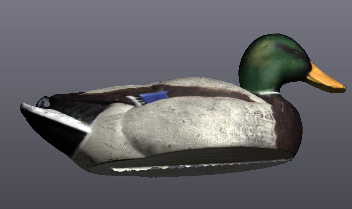
Something that seems to collect on co-workers desks (as well as my own) are 3D Printed knick-knacks. I try to limit this to old material that we are trying to use up, but occasionally a project pops up that catches my eye. In this case, a duck decoy was sent to me along with other parts for training purposes on our GO!SCAN 50 3D Scanner. This scanner collects point cloud data as well as 24 bit color.
After scanning, this model needed some cleanup in order to make it worthy of a display piece on someones desk. The original part had a ballast on bottom that I already removed.
A few areas that need attention:
- The bottom was not flat, we’ll need to make a perfectly flat bottom so the rests without rocking.
- The eyelet in the back where the decoy could be tied to a rope.
- A few areas around the head had small dings and the bill needed cleanup from jagged edges.
- Lastly, we’ll export our model for printing.
First things first, we’ll need a plane on the bottom. I started by by sending the scan over to VX Model to make my modifications and creating a plane on the bottom.
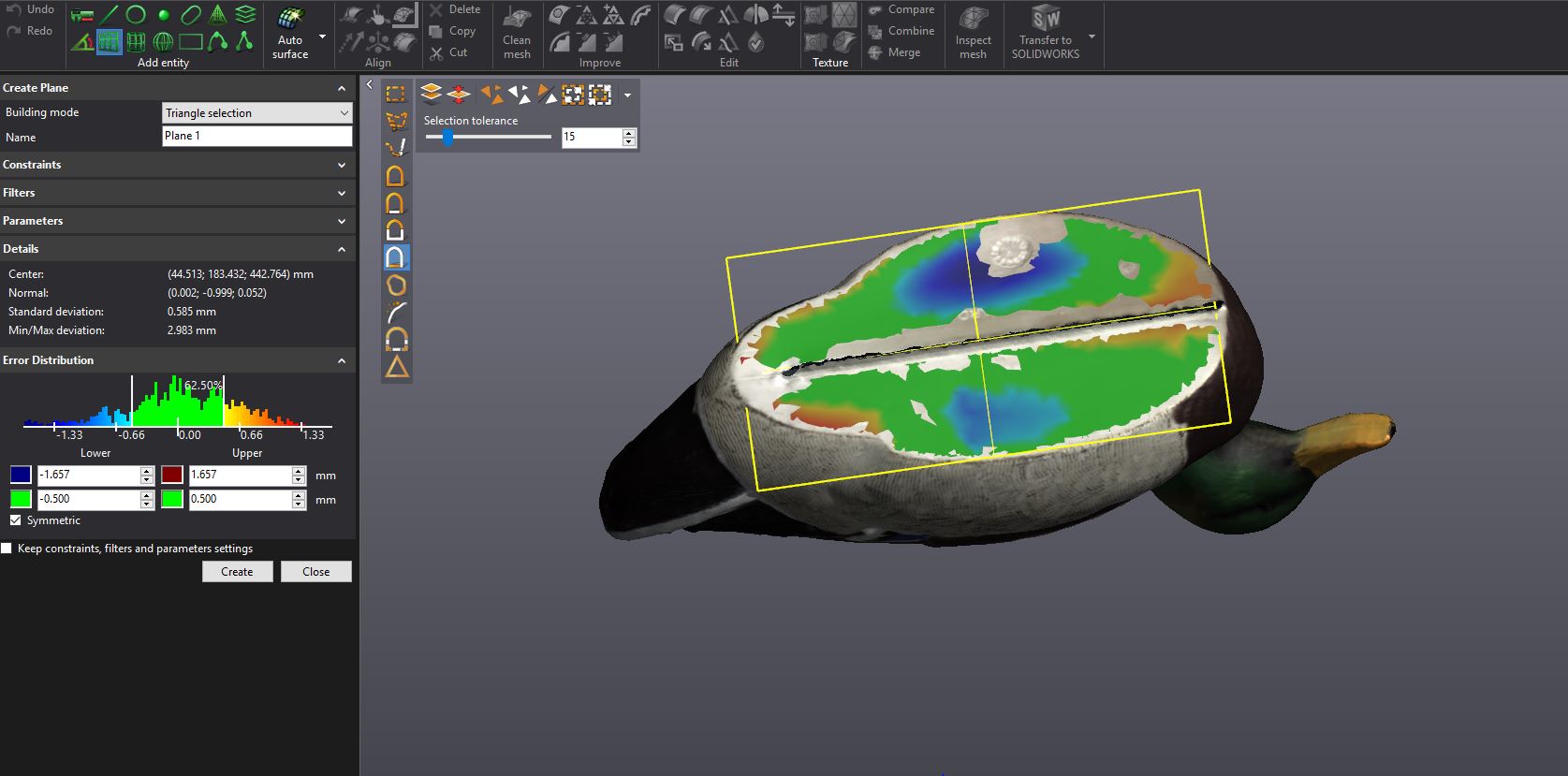
You can see with the error distribution on the plane, how far out we are for a flat plane. Over 3mm total deviation.
Using the “Cut Plane” command, we’re able to cut our model, and actually offset the cut in order to remove the warped areas.
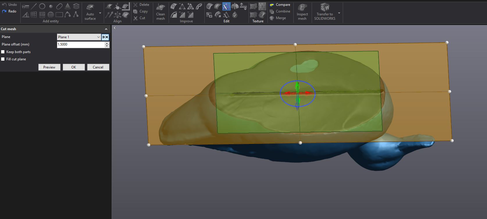
We’ll select our plane, making sure to reverse the normal, and offset by 1.5mm. You can use the preview button to make sure everything looks right before committing to the cut. Notice that we lose the color texture once we start modifying the geometry. This is is normal and we can reapply the texture once the model is finished.
After the model is cut, we’ll end up with a small floating piece we can select and delete. If you can’t see the hole at this point, you might need to hide the scan mesh data. We can also hide out plane since it has served it’s purpose.
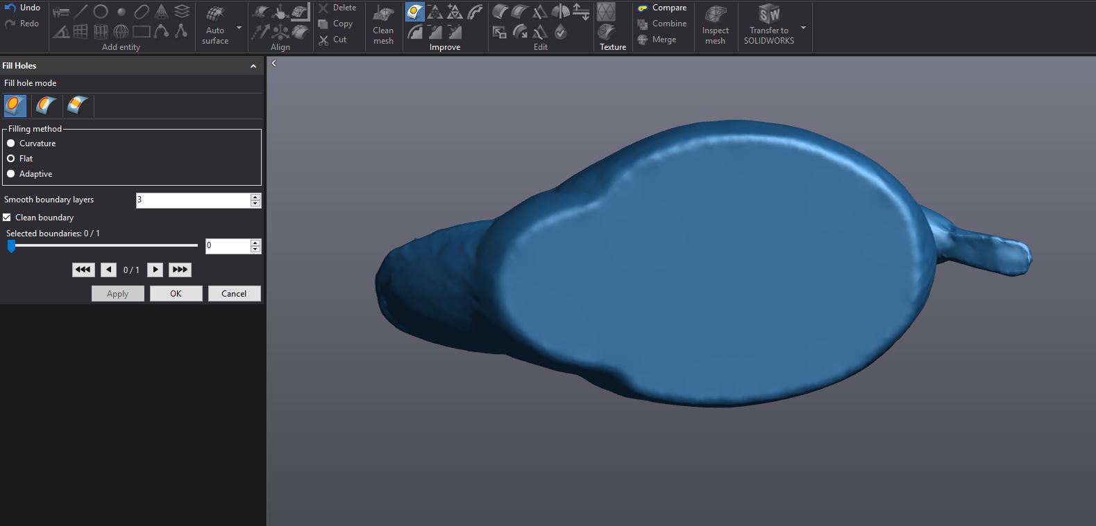
Since we have a nice planar cut, we can use the Flat option in the “Fill Hole” command”. I also use the Clean Boundary option to help reduce any jagged edges we might not be able to see.
From here, I focused on the eyelet in the back. I used the “Brush” selection tool an grow/shrink commands to capture the eyelet.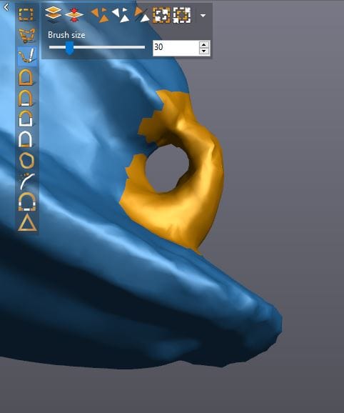
After verifying my selection, I clicked delete (or hit the delete key on the keyboard) to remove the eyelet. I used the “Fill Hole” command again, using the Curvature method in the dialog box.
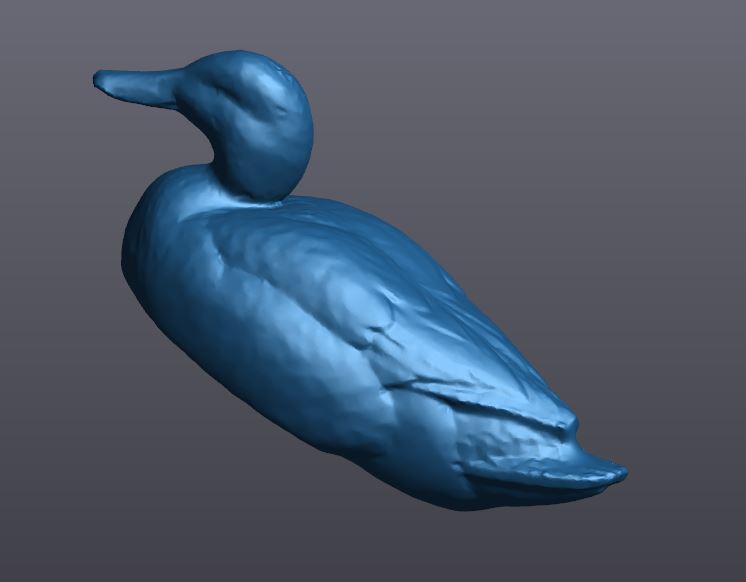
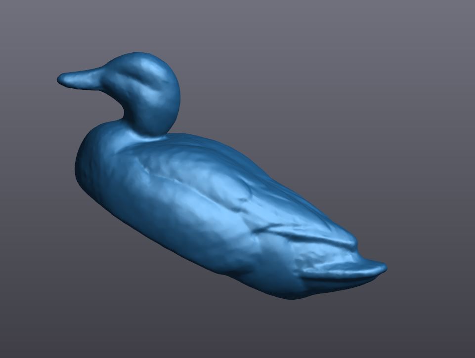
One of the final steps is to try to smooth out the model as much as possible. You can see the sharpness of some of the areas, I didn’t want that to printed. I used the “Remove Spike” and “Smooth Mesh” commands, both at maximum settings. Below are the results from smoothing. You can see how smooth the model has become.
Since we are printing, I like to check the model to see if its “Water Tight” which means the model is a solid printable body. In this case, I get confirmation that my model is already water tight. A good scan up front can really help in this regard.
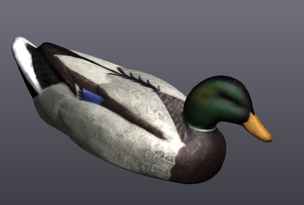
Once you are satisfied with your model, click the “Apply Texture” command to reapply the color texture from the the original scan.
To get this over to GrabCAD Print in order to print this in color on our J750, use the File-Export command and choose VRML as the file type.
Here is a view in GrabCAD Print with a 25% scaled version of our project. You can verify the final dimensions in the scale command, at the 25% we’ll be a little under 4″ which is a good size for a desk piece. We can also use standard windows hot keys for copy/paste in order to print more than one.
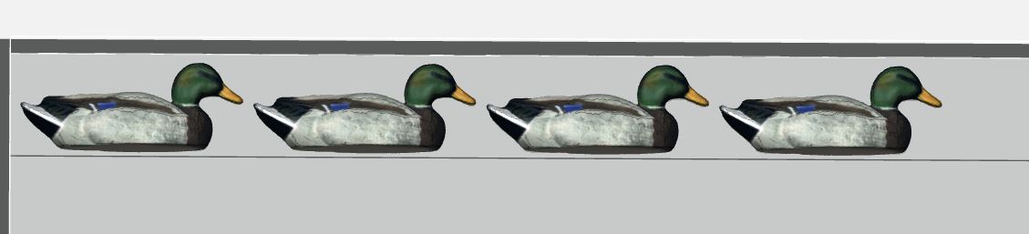
In our industry, we call this having our ducks in a row!
Stay tuned for more “How-tos” and bad jokes in coming blog posts.
Jeremy Marvin
Additive Manufacturing Application Engineer
Computer Aided Technology, Inc