STL Output Settings for CAD (Updated for 2018)
Happy new year! This information is borrowed from a blog post I wrote a couple years ago, it still holds true if your intent is to end up with a printable STL from SOLIDWORKS. However, if you don’t need to make high level changes to toolpaths, like you might see in Insight, you can open native CAD files (including SOLIDWORKS Parts and Assemblies) within a software package called GrabCAD print. This saves time and bypasses the need to worry about file conversions.
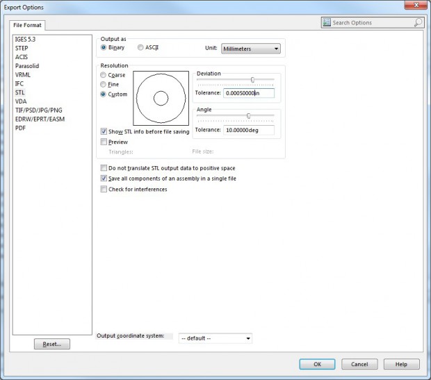
CAD comes into play when we think about what we need to print. Currently, the industry standard file format for 3D Printing is the STL (Standard Tessellation Language) file. All major CAD packages can save or export in the STL format, including SOLIDWORKS. Simply click File-Save As-STL. Once the STL file type has been selected you’ll notice an options button appears. Clicking this options button shows you all the settings we can change regarding the STL File itself.
Quick Tips when setting up your STL Output
1. Use the Binary option to save disk space, it reduces the file size by a ratio of 6:1.
2. The STL itself is unitless. SOLIDWORKS will output in the specified units, no matter what unit we use in our model. When we bring the model into our 3D Printing software, we’ll need to specify the units used. If the parts come in really big or small, the software will ask you to confirm.
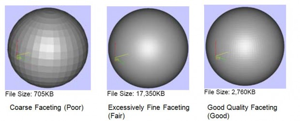
3. Stratasys recommends a Deviation tolerance of .001″-.012″ [.03mm-.3mm] I generally set the resolution to Custom and use .0005″ which is a touch smaller than they recommend. The files tend to grow very fast when you get down much smaller than that. The bigger the file the longer it takes to process in the 3D Printer software. [I have a model from a customer that was 750mb and took 30 hours to process. We need to strike a balance between getting a high tolerance part and keeping file size/processing time down.]
4. Stratasys recommends an angle tolerance of 5-10°. The default in SOLIDWORKS is 10° so I leave this alone.
Below is a small example explaining the Deviation (chordal tolerance) and the Angular tolerance. This is the max difference allowed between the faceted surface and the SOLIDWORKS Model.
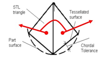
We can’t print a model better than the STL, so it is always good to check the options before saving the model, and verify the STL looks good before processing.
Jeremy Marvin
Additive Manufacturing Application Engineer
www.cati.com