3D CAD Design For 3D Printing - Tips, Tricks, & Techniques - Part 1 of 3
Designing for Additive Manufacturing can be somewhat different than designing for traditional subtractive processes (Mills, Lathes, etc.). We will break this process down into three parts that impact your design. The three parts will focus on Design Considerations (part 1), Exporting Data (part 2) and Build Preparation (part 3).
As a designer you have numerous design considerations for your creation. However, for Additive Manufacturing (AM) let’s just concentrate on these three design considerations that make a difference in 3D Printing; Technology, Material, and Geometry.
Technology:
Looking at AM technologies, your first question might be, “Why are there so many 3D printers in the market place to choose from?” Four simple answers… Each 3D printer has different capabilities, each 3D printer has different materials, each 3D part has different applications, and each 3D part has different geometries. 3D Printers can be as unique as the parts you design; different sizes, different shapes providing different functions.

Material:
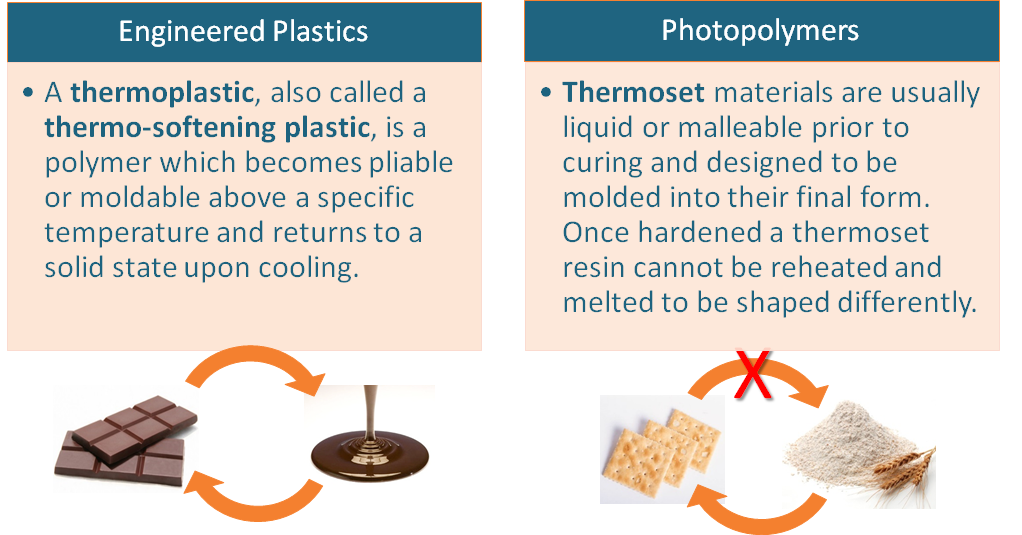
Determining which 3D printer to use can often begin with material selection. For plastic parts, there are basically 2 types available; Engineered plastics and Photopolymers it is important to understand the difference in their properties as a Thermoplastic and a Thermoset respectively.
Geometry:
All 3D Printers are a layering process. Knowing the layering thickness and drawing resolution of the 3D printer will aid in your consideration of geometrical design. FDM (Fused Deposition Modeling) using Thermoplastics will build in .005, .007, .010, .013 or .020 inch layers depending on the particular machine and material. While PolyJet technology using a inkjet printing head with Thermoset plastics can build a much finer layers in 16, 28, 30 or 36 micron depending on the particular machine and material.
Now let’s look at some of the most common geometries; wall thickness, angles, holes and fine detail and how they relate to 3D Printing, specifically FDM and PolyJet.
Wall Thickness:
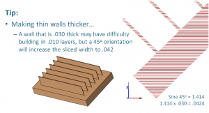
For FDM the only limiting factor for wall thickness is the width of the extrusion. With advanced software the width can the edited smaller or wider. As a rule of thumb, the extruded contour width is typically 2 times the layer thickness. For wall stability it is advisable to have at least 2 contours to create the wall. This means that your design standard should be about 4 times the layer thickness. For example, if building at .010 inch layers then a .040 inch minimum wall thickness would be advisable.
With PolyJet, printing at a high resolution of 1600 dpi, extremely thin walls can be achieved. Your design limitation here becomes fragility from handling or cleaning the models. From personal experience the taller the wall the thicker it needs to be. For tall thin walls, consider a 1-degree angled draft on the wall to add stability.
Self-Supporting Angles:
Regardless of the 3D printer you are using it is drawing a 2D image in multiple layers to create the 3rd dimension. With this in mind, most printers will require some kind of support or brace to prevent overhanging layers on top of a previous layer from collapsing. Some machines, typically powder based machines, will use the unused material itself as a support for the next layer.
Some designs can be ‘self-supporting’ and not require a support system . Understanding Self-supporting angles can be crucial in your design to make parts more producible with faster material savings, faster build time and less labor in post-processing. This ‘self-supporting’ design is dependent on three variables; technology, material and layer thickness. For example, because PolyJet is printing drops in micron layers every down-facing surface must be supported, otherwise gravity will cause it to fall. But other technologies such as FDM can have enough strength to build a layer that slightly overhangs the previous layer to produce an angle.
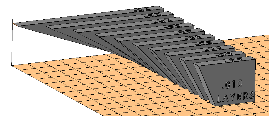
Figure 1
So the question now becomes, “How much of an angle can be built without requiring support?”. A simple test will give you the answer. Creating a part with a series of angles (20o – 65o at 5o increments), positioning it as shown in Figure 1 and editing the parameters to build with no supports will easily show the maximum unsupported angle that can be built for that particular technology, material and layer thickness.
The part shown in Figure 2 was built with FDM using ABS material at .010 inch layers. Notice that even with no support the part built without a crash, but some surfaces on the shallow angles are ‘sagging’ and are not acceptable without supports. This gives you an idea of what angles you can incorporate in your design to minimize support build time and cost.
However, what if we change just 1 of the 3 variables (Technology, Material and Layer Thickness)? The same part shown in Figure 3 was built with FDM using ABS material at .007 inch layers. Changing just 1 variable of building at .007, instead of .010 inch layers we can produce a good surfaces even on the shallow angles. This is because with smaller layers the overhang is not as great as with thicker layers.
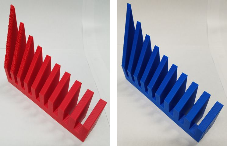
Figure 2 and Figure 3
Figure 4 and figure 5 below show a good example of rotating a feature on an angle to take some advantages of designing for 3D Printing. The feature on the left is a traditional design that would be incorporated in Subtractive manufacturing, while the feature on the left is the same exact geometry rotated 45 degrees for a more efficient printing with Additive manufacturing.
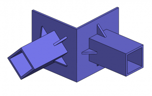
Figure 4
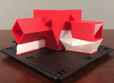
Figure 5
Holes and Radii:
When 3D printing holes with FDM it is always desirable to position the hole axis perpendicular to the platform. Unfortunately some designs (channels for wiring ,tubing, fluid, air, etc) require that the holes be sliced in a horizontal orientation. So can supports be eliminated in these holizontal holes?
From the section above; Self-Supporting angles, you will remember that structural supports are dependent on three variables; technology, material and layer thickness. This is especially true for horizontal holes, being assembled in layers. A horizontal hole, with the axis parallel with the build platform, is sliced into layers with half of the hole requiring an overhanging layer. As we previously discovered some overhangs can be built without a support structure.
So the question becomes, “How large of a horizontal hole can be built without requiring support?”. A simple test part can show you what to expect.
Creating a part with a series of holes (0.125 – 1.000 inch at 0.125 inch increments), positioning it as shown in Figure 6 and editing the parameters to build with no supports will easily show the maximum unsupported hole that can be built for a particular technology, material and layer thickness.
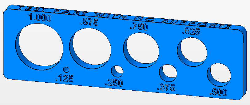
Figure 6
The part shown in Figure 7 was built with FDM using ABS material at .010 inch layers. Notice that even with no support the part built without a crash, but some surfaces on the larger holes are ‘sagging’ and are not acceptable without supports. This gives you an idea of what size horizontal holes you can incorporate in your design to minimize support, build time and cost.
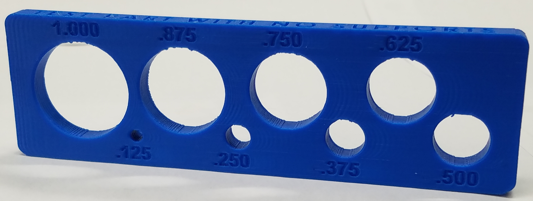
Figure 7
Fine Detail Text:
Part numbers, lettering or text are often incorporated into a part design. This level of detail can be 3D printed easily with PolyJet at 1600 DPI and Micron layers. However, for FDM you must remember the default extruded contour width is directly related to the slice thickness. As previously described in the Wall Thickness section above, for .010 layers the default extruded contour width is .020 inch. Therefore, your lettering should be at least .020 inch wide.
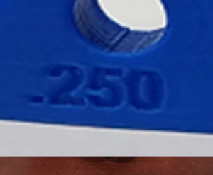
Figure 8
For most 3D printing technologies, orienting the text fac-up yields the best result. But, for text that is vertical, notice in the previous example used in the Holes & Radii section above that the vertical text shown in Figure 8 built crisp and well defined even being built standing up with no supports. This is achievable because the text is recessed only .020 deep. Again, when FDM is sliced at .010 layers, the typical default extruded contour width is .020, by limiting the text depth to no more than 1 extruded co ntour width (or .020 inch deep) this small overhang can be built without supports.
Fine Detail Sharp Edges:
Another aspect of fine detail is a sharp edge geometry. In 3D Printing, a crisp sharp knife edge is limited to the technology. The lack of a sharp edge is often confused as an accuracy issue, when it is really a mechanical limitation. However, if understood properly it can be overcome with a simple design correction.
Using a simple part with a 5o angle 4 inches long as shown in Figure 7, let’s look at how the drawing diameter can affect accuracy.
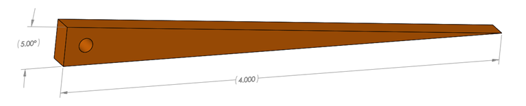
Figure 9
A sharp point or edge is limited by the drawing diameter of the technology. This is true regardless of the technology; extruded filament, laser focus or material particle size. Figure 10 below shows the toolpath of the CAD model that will be drawn with a .020 diameter extruded filament.
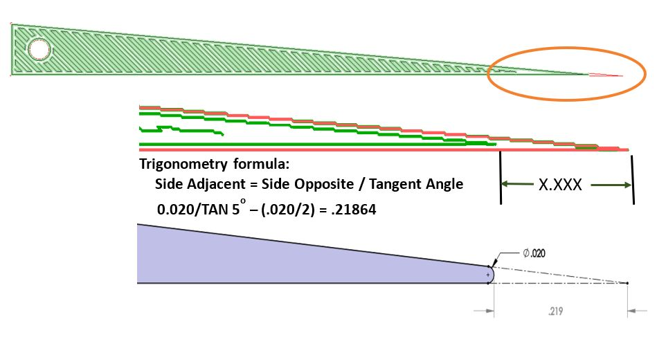
Figure 10
However, the designer can overcome this geometrical limitation in the CAD model by simply extruding a flat feature the thickness of the drawing diameter. Figure 11 below shows the revised part and Figure 12 shows the toolpath to create a more accurate model. If a sharp knife edge is required, it can now be sanded with the extra material and hold the required accuracy.
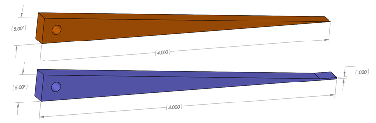
Figure 11
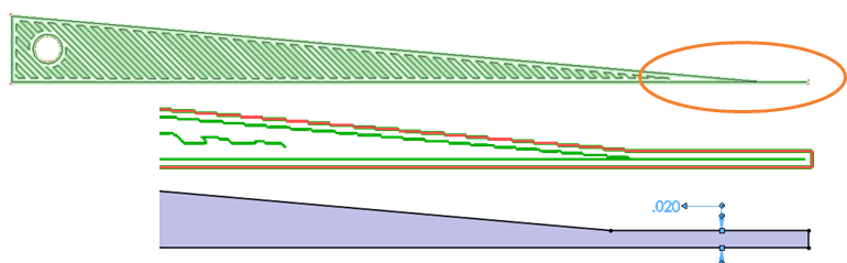
Figure 12
While this does not cover all geometries or design considerations, hopefully it is a beginning for the designer to start thinking about how to incorporate 3D Printing in their part creation. In the next blog, part 2, I will discuss exporting the data for 3D printing. This can be equally important to define the form, fit, and function intended for the designed part.
Mark Abshire
Sr. Application Engineer, Additive Manufacturing
Computer Aided Technology, Inc