SOLIDWORKS Simulation Case Study: Stress concentrations occurring in places they shouldn’t or too high?
Finite Element Analysis (FEA) results are dependent on model, material, and boundary conditions. However, the boundary conditions have the greatest effect on the results. The boundary conditions in SOLIDWORKS Simulation must reflect the conditions in the physical experiment. A good example is the scissor lift shown below (Figure 1). As we all know, scissor lifts are designed with legs that are collapse and expand. These “legs” are pinned together. If a load is placed on the lift, then the whole structure will collapse unless the hydraulic piston is pressurized to hold the lift.
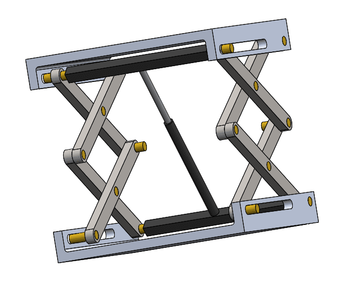
Figure 1 Example Scissor Lift
I created a study, placed a load on the top, meshed with a curvature-based mesh, and then ran the study. The quantity of load is not important. The stress concentrations would be similar but at a lower or higher magnitude depending on the size of load. We cannot take the stress results for granted. Simulation results must be interpreted because they may not be legitimate. The adage, “garbage in, garbage out” applies also to simulation.
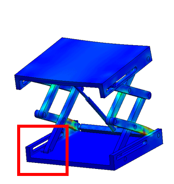
Figure 2 Something Fishy
Upon inspection we notice that something odd is going on for the bottom supports. Notice the red square in Figure 2 above, and a zoomed version in Figure 3 below.
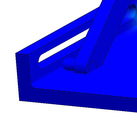
Figure 3 Something Fishy; Zoomed In
At this point, we have not setup any custom contact sets. We are only using the bonded global contact set. But this pin does not appear to be bonded to the slot. When cylinders are in tangent contact with adjacent faces they don’t always bond they way they should. To correct this, I created a bonded local contact set between the cylinder and the 2 tangent faces to each side of the lift (Figure 4 below).
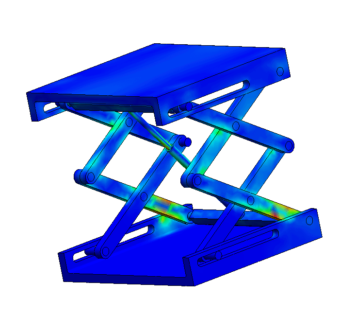
Figure 4 Update Lift with bonded local contact set
Now we see that the cylinders are in contact with the slots and appear to be holding the lift as it should. But we are seeing stress concentrations in areas that we probably shouldn’t, because the “legs” are not holding the lift, it is the hydraulic cylinder that is supporting the lift.
To get a realistic model (model is more than just the shape; a good mathematical model will also account for the movement and support in the mechanism) I replaced each of the bonded contacts between the leg segments with no penetration. The leg segments can slide past each other and the joints can rotate. Having a bonded contact will not adequately model the sliding and rotating behavior. Bonding bodies are essentially welded or glued components, rather than the pinned components we have within the legs of the lift.
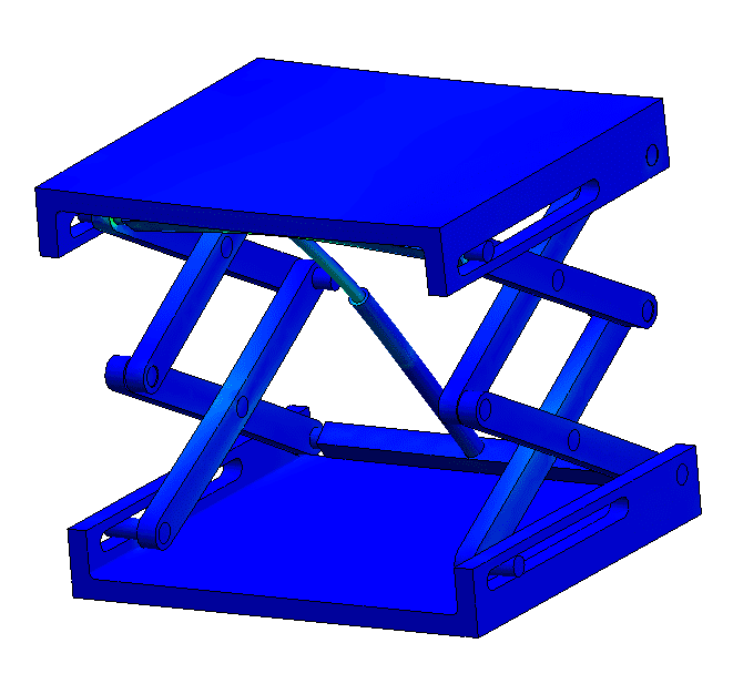
Figure 5 Update Stress Concentrations
Now, in Figure 5, we see that the stress concentrations no longer are in the leg segments. These stress concentrations now are where they should be in the cross bar that supports the hydraulic cylinder. Which you can see in Figure 6 below.
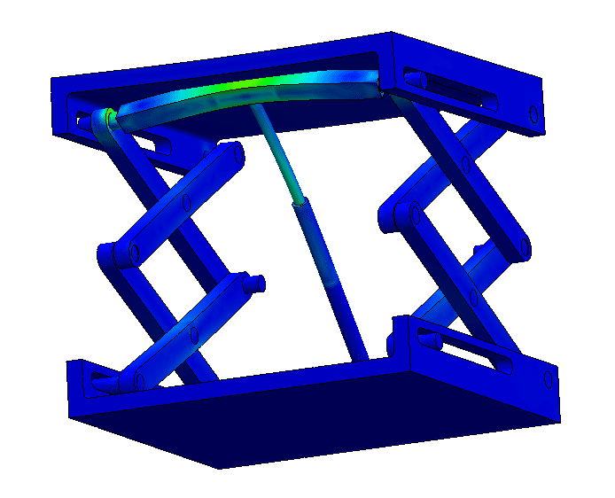
Figure 6 stress concentrations in the cross bar
Often troubleshooting a stress plot that looks off is a sequential process. My hope is that this blog article will provide insight into the troubleshooting process.
Matthew Fetke, CSWE
Application Engineer – Simulation
Computer Aided Technology, Inc