PLA plastic and replacing the PLA Head in your F123 Series Printer
PLA works well at high speeds, specifically fast-draft mode on the Stratasys F123 Series. Get quick concept verification and design development while keeping material expenses down. Available in transparent colors, use PLA to 3D print see-through prototypes such as tail lights and blinkers. PLA offers good tensile strength, high stiffness, a low melting point and low HDT, which means less heat and power are required to print.
Download the Spec sheet here: http://www.stratasys.com/-/media/files/material-spec-sheets/mss_fdm_pla_0118a.pdf
Download the Safety Data Sheet here: http://www.stratasys.com/-/media/files/safety-data-sheets/pla-safety-data-sheets.zip
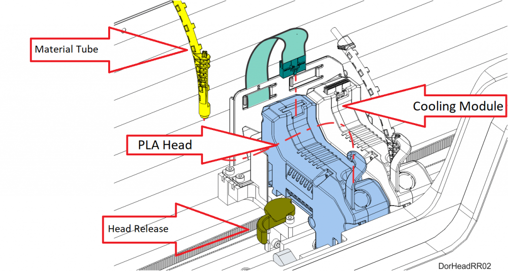
The process for replacing a PLA head varies slightly from the process for replacing a standard head. The PLA head must be installed into the model head location within the gantry. A cooling module is used in conjunction with the PLA model head and must be installed into the support head location. The PLA head extrudes both model and support structures.
The instructions listed below are a guide on how to change out the PLA head and cooling module. The procedure is the same for replacing both the PLA head and the cooling module.
- Unload both model and support material from the printer.
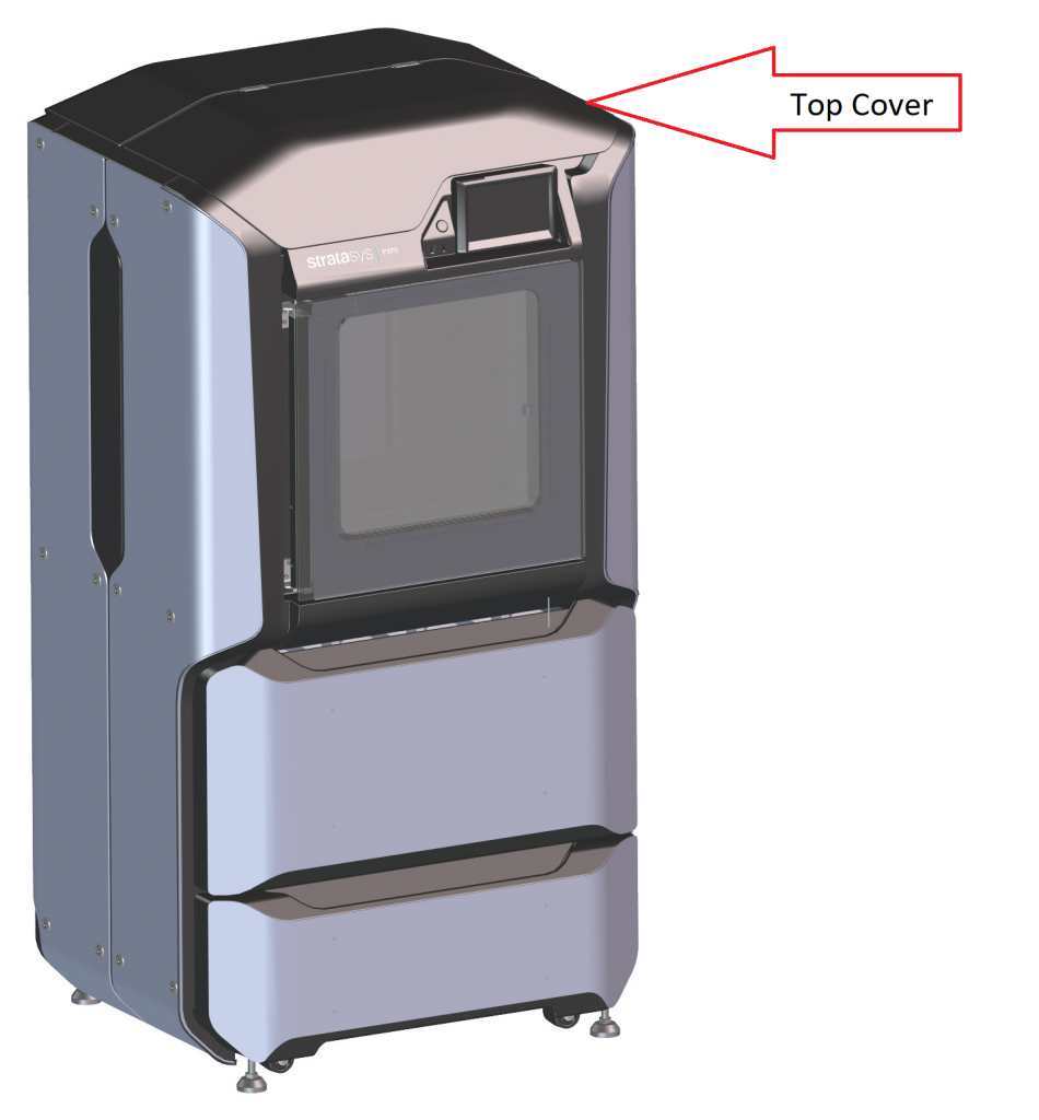
- With the printer powered ON, open the top cover
**Note: Replacing a head while the printer is powered ON will ensure that an Automatic Tip Calibration is performed after the replacement process is compete. Power is automatically removed from the head and all motors when the top cover is opened.
- Depress the release tab and unclip the head ribbon cable for the head that will be replaced (PLA head is on the left. The cooling module is on the right ).
- Disconnect the material tube for the head that will be replaced.
- Unlock the head release lever for the head that will be replaced.
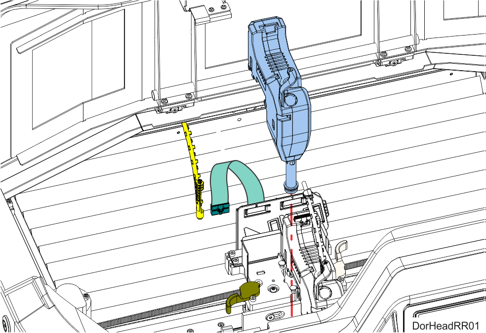
- Pull the standard head assembly out of its position within the gantry and remove it from the printer. Remove head.
- Insert the PLA head assembly into the vacant location within the printer.
- Lock the head into place using the head release lever. Press the lever securely closed to ensure that the head is properly seated.
- Connect the material tube to the new head assembly.
- Insert the head ribbon cable connector into the new head assembly ensuring it is fully seated in the head and the connector retention latch engages.
- Follow the above procedure for replacing the cooling module.
- Close the top cover.
- An Automatic Tip Calibration will automatically be performed prior to the start of the next build following a head replacement. Please note that the printer must be powered ON before calibration can occur.
Note: If a head was replaced while the printer was powered OFF, an AutomaticTip Calibration does not occur after closing the top cover, you must manually initiate the calibration. See your user’s guide for instructions. It is also recommended to perform the manual calibration after a head is replaced per the user’s guide. If you don’t have a user’s guide please email support@cati.com and we will be more than happy to send you a digital copy.
John Dessoffy
Field Service Manager
Computer Aided Technology, Inc