How to Make a Sphere in SOLIDWORKS
 Historically, whenever I’ve taught our SOLIDWORKS Essentials training class, I’ve imparted to following advice: Let’s start simple and let’s start with the basics. Oh, but you design airplanes? Dredging systems? Floor plans? To me, it doesn’t really matter. You can’t skip steps. If you start out small, you can scale your skills swiftly.
Figuratively-speaking, that means you should start with primitives. In computer programming, this means understanding data types like integers (1, 5, 17, etc.) and strings (“Hello world!”) first of all. In 3D CAD modeling, this means learning the primitive shapes, like how to model cubes and how to model spheres in SOLIDWORKS.
Modeling a sphere is relatively simple, and it’s a great lesson in how to effectively use the Revolve Boss/Bass tool in SOLIDWORKS.
In the SOLIDWORKS Essentials course, we cover how to make axial revolve shapes fairly early on during our lessons. We go as far as making a full handwheel, equipped with a handle, hub, and spokes.
But again, let’s not start there, exactly. Let’s start with a primitive.
The looping GIF below shows how you can easily make a sphere.
In outlined form, here are our steps:
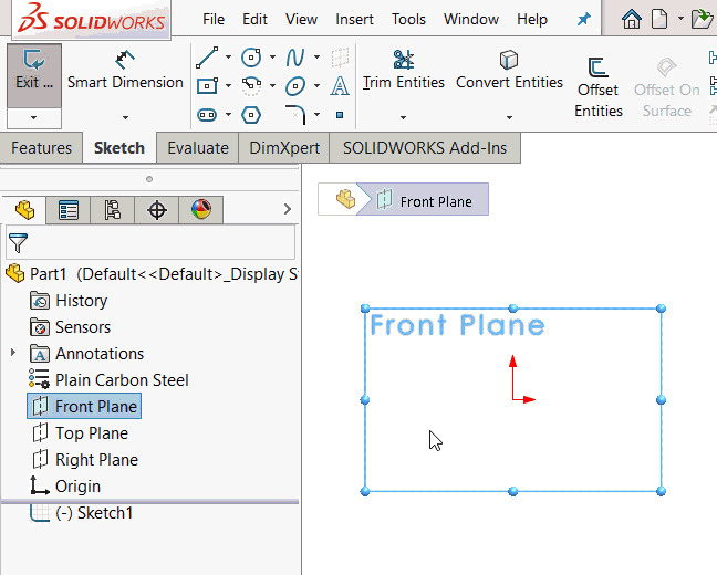
- Select a sketch plane (such as the Front Plane)
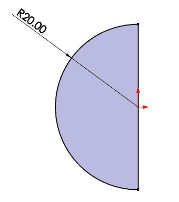
- Sketch a semicircle
- Go to the Features tab on the CommandManager. Select “Revolve Boss/Bass”
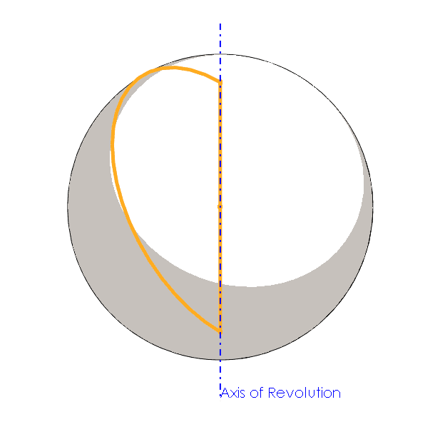
- Select the line in the semicircle as the axis of revolution. Specify your revolution amount, then press the green check to generate the sphere
Here’s how I think about revolve shapes. Let’s take a cross-section of the desired end shape, then cut the cross-section in half. There’s your sketch profile.
As a matter of best practice, you should probably add some dimensions to express what we like to call your “design intent.” In this example, this basically means: “If the intended diameter/radius of this sphere is 100mm, make it so at the sketch level.”
While we’re focused on spheres, let’s continue on to tackle another fundamental concept of CAD modeling in SOLIDWORKS. Often, we have shapes that are hollow; often, we have shapes that are full. So, how do we tell SOLIDWORKS what we want when sketching our shapes and performing revolve operations?
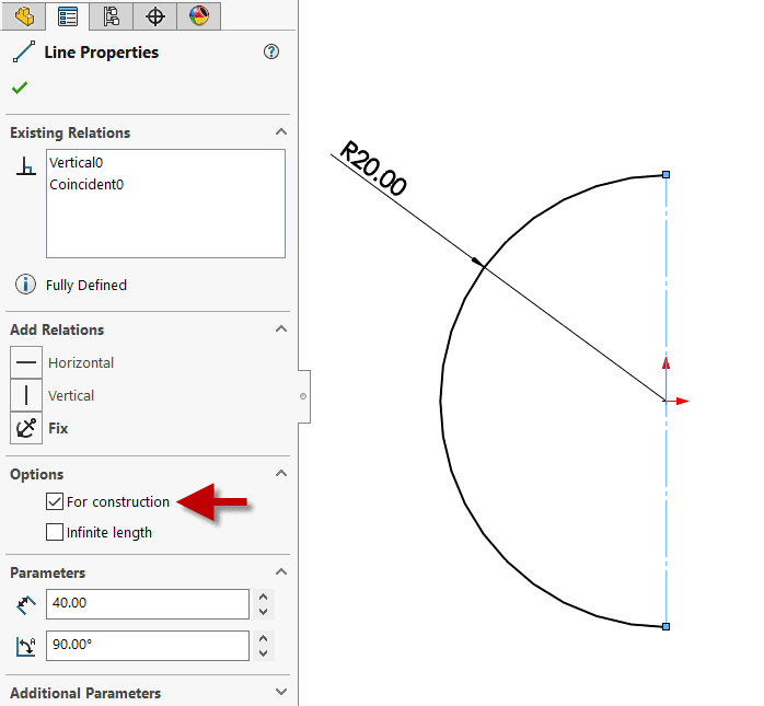
In the example submitted above, we have a full sphere. It is not hollow inside. There are a couple of ways to hollow out a shape after it has been created (see the Shell feature, for instance). However, you have control over this while making the shape.
If we designate the axis – in this case, the line completing the semicircle – as ‘construction geometry,’ we are made aware that the forthcoming shape will be hollow. The thickness settings shown below assign the wall thickness of the resultant sphere.
To verify your results, you can use tools like Thickness Analysis (under the Evaluate tab on the Command Manager). If you just want to see a visual of the hollow sphere, feel free to leverage the Section View tool to see the cross-section of your new shape.

Related Articles
How to Mirror a Part in SOLIDWORKS
How to Change Material in SOLIDWORKS: Customized and Standard
About the Author
 Sean O’Neill is a Senior Support Engineer at Fisher Unitech. He is a Certified SOLIDWORKS Expert (CSWE), a SOLIDWORKS World Presenter, and a former SOLIDWORKS VAR Marketing Manager. You can follow him on Twitter: @ServicePackSean.