Calculation of Abnormal Springs with SOLIDWORKS Simulation
In mechanical applications, springs are very common. Anything from spaceships to consumer products is likely to have a spring in it somewhere. For most purposes, springs can be expressed mathematically with a “stiffness” value often denoted “K.” This stiffness is simply a relationship between the force needed to generate a specific displacement from the spring, Force= K * Displacement. When buying springs, usually the supplier or manufacturer will provide data about the spring’s stiffness value. However, the use of common springs is not always possible with modern designs. In this blog we are going to discuss a custom spring, and how we can use SOLIDWORKS Simulation to figure out the spring’s stiffness, and how to apply that stiffness via a spring connector in Simulation.
Let’s start with an atypical spring design. For this, I reached out to my colleague Fred for some inspiration on making a CATI custom spring.
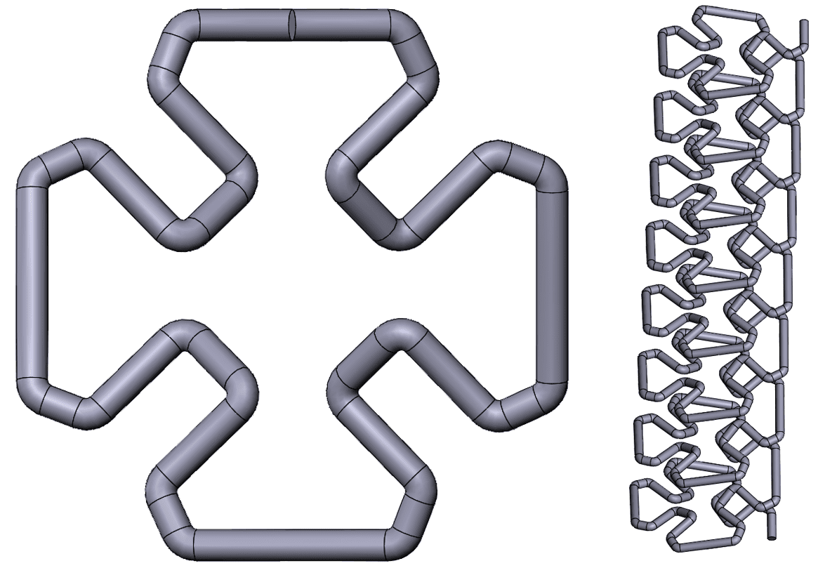
Often times, it is quite difficult to simulate a spring. There are all sorts of mesh parameters that must be considered, fixturing can be difficult, and if there any contacts involved the calculation can be even more demanding. For this reason, SOLIDWORKS Simulation has a “Spring Connector” feature that allows the user to bypass all of those difficulties. All the user has to do for this connector is to define the spring interfaces and enter the theoretical stiffness values for the spring. There is a bit of extra functionality in the connector which will be covered in an upcoming blog. For now, the goal is to simulate the spring as a solid body so that we can extract the spring constant. From there we will apply that spring constant as a connector between two plates to validate the results. Let’s get started!
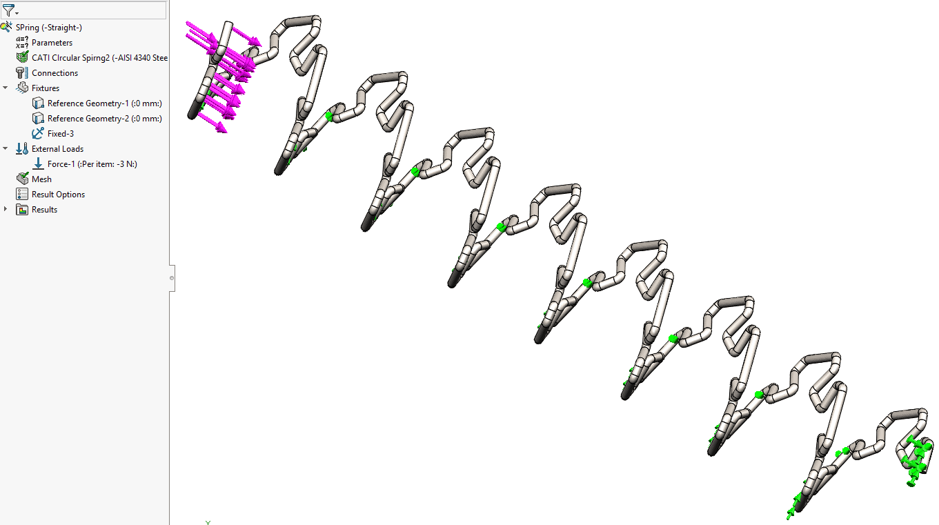
In order to simulate a spring all that is needed is a basic linear static analysis. With a fixed geometry on one end and planar fixtures on two sides, the structure is fully restrained. Simply add an axial force to the assembly and create a sufficient mesh, and the structure is ready to run!

From the results above, we can confirm that the spring is indeed behaving as we expect and validate our results. In order to get a good idea of the actual spring constant, I set up a simple design study that varies the applied force and records the resulting displacement. For more information on design studies, see here. Once completed, the results can be seen below.
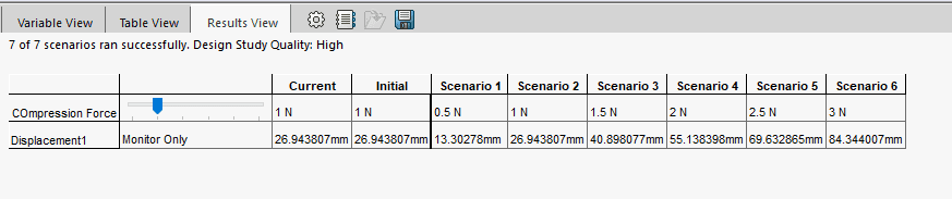
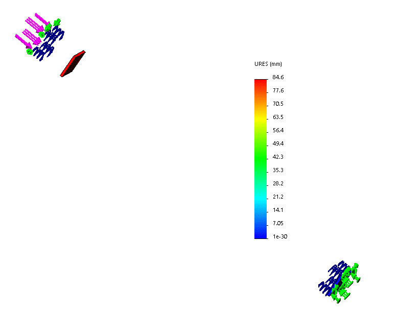
I exported this data into a CSV where I calculated the average spring stiffness value, K, as 0.036605 N/mm or 36.60497 N/m. We will use the 3N load as the benchmark for the virtual spring connector, so we are looking for a displacement of around 85mm. For the setup, I modeled 2 plates with an initial separation. I applied a spring between the 2 faces and entered the axial stiffness value (A.K.A. the spring stiffness value) that we had calculated.
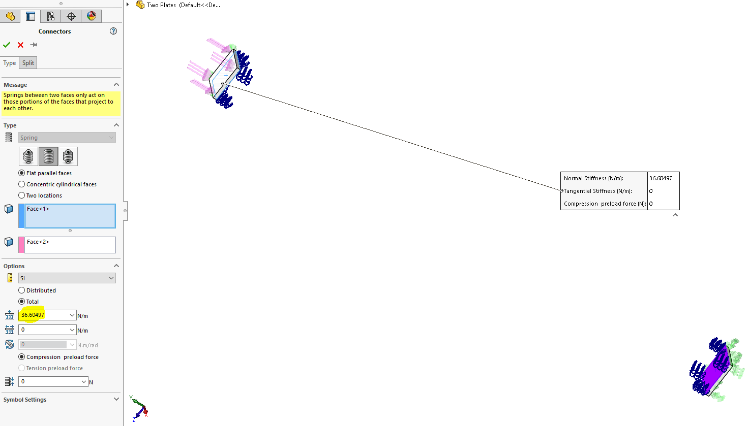
Once the study ran, I received a maximum displacement of 84.6mm. This result was within 0.3% of the solid body deformation, so our results are indeed correlated.
Thank you for taking the time to read this blog about extracting spring constants using SOLIDWORKS Simulation. For more information on the software’s capabilities please keep up with our blog, or visit our website here. Please contact us if you have any questions or are interested in seeing a demo!
Matt Sherak
Applications Engineer, Simulation
Computer Aided Technology, LLC