Printing with Vivid Vero – White centers, Translucent and Hollow parts
The introduction of the Vivid Vero colors in the Stratasys Polyjet materials lineup came the ability to print transparent colors and an even larger range of colors. However, using the vivid materials without considering the way GrabCAD Print handles them.
When printing non-textured STL, VRML or SLDPRT files, GrabCAD Print will print these files by default with a thin colored shell and a white center (VeroWhite, VeroPureWhite). This wouldn’t be an issue with opaque materials, but the transparent materials the core is easily noticeable. This white core is not visible in GrabCAD Print so knowing when the white core will print can save time and material.
To test some different strategies for printing, a print job in GrabCAD Print was created using two main shapes: a hemisphere and a square pyramid. Each of these shapes was also sliced to create parts with multiple solid bodies. The SOLIDWORKS models of the shapes are displayed below.
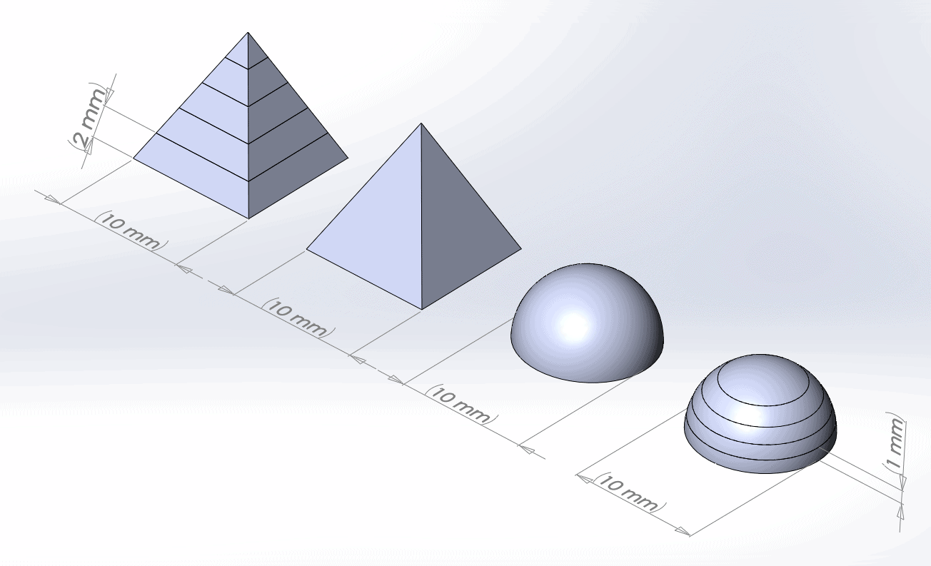
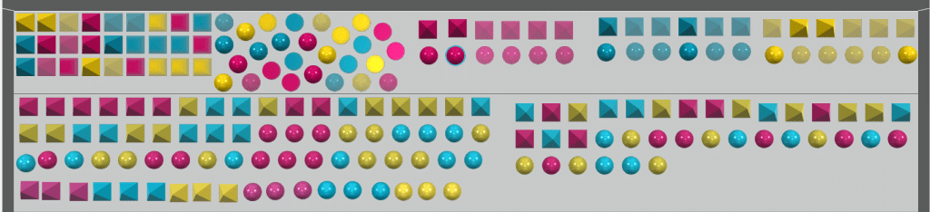
Each of these parts was printed in 3 different file formats, 3 different colors, 3 different GrabCAD Print color types, with 3 different GrabCAD Print model settings. A preview of the tray is shown below.
Each shape was saved in 3 different formats: the default SOLIDWORKS file type SLDPRT, as a high quality STL, and as an untextured VRML. Since VRML and SLDPRT can incorporate multiple solid bodies, these showed up in GrabCAD Print as separate solid bodies. These files were printed in 3 main colors: Magenta, Yellow, and Cyan. Since GrabCAD Print has different types of color settings, the parts were also printed using 3 different settings in GrabCAD Print:
- Purely Vivid colors; VeroMagentaV, VeroYellowV, VeroCyanV.
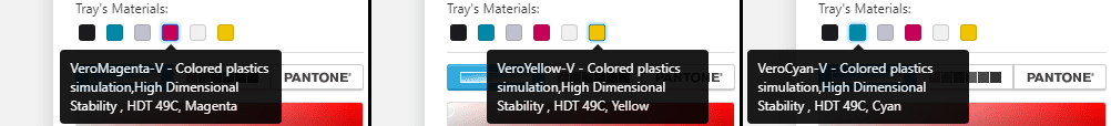
- Colors similar in hue to the Vivid colors (#F1209B for Magenta, #E7D24D for Yellow, and #18CDEF for Cyan)
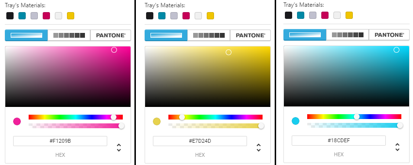
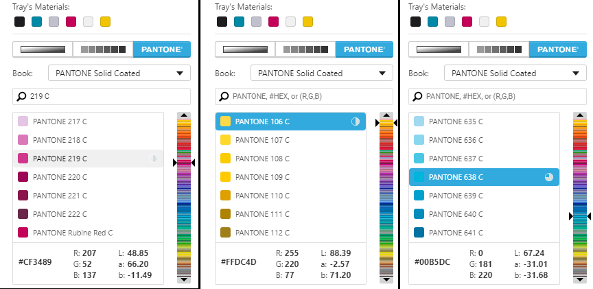
- PANTONE colors similar in hue to the Vivid Colors (219 C for Magenta, 106 C for Yellow, and 638 C for Cyan)
In addition to printing the different shapes in different file formats and different colors, each color/file format/shape was printed using 3 different model settings:
- Without changing any of the settings
- With “Translucent” checked
- With “Hollow” checked (which automatically checks “Translucent”)

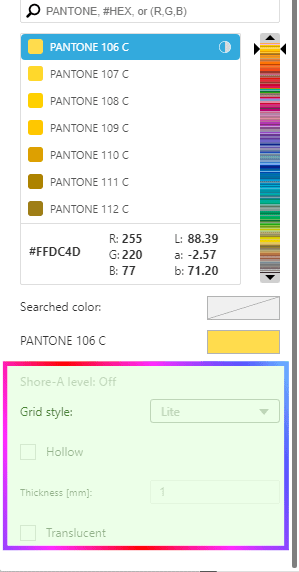
Since the PANTONE colors do not allow the “Translucent” or “Hollow” boxes to be checked, the PANTONE parts were only printed with default settings.
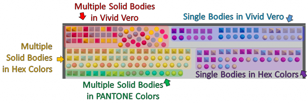
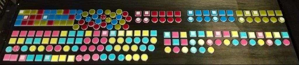
With all these different configurations, the print tray can be roughly divided as follows. (Single body PANTONE colors and single body STLs were not printed to keep things simpler).
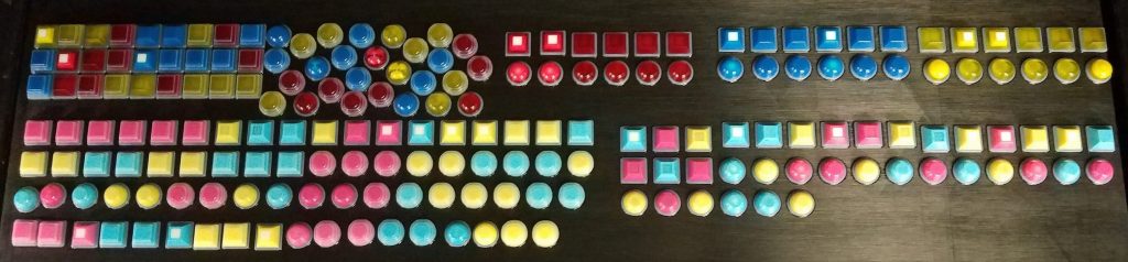
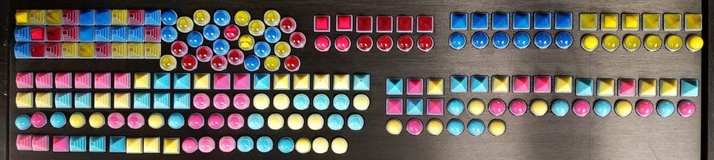
Below are some pictures at various points in the print.
Below is a time-lapse of the print.

Media error: Format(s) not supported or source(s) not found
Download File: https://appgoengcab4ab8d0951.blob.core.windows.net/blobappgoengcab4ab8d0951/wp-content/uploads/2019/12/timelapse-project.mp4?_=1Here are some observations from the print:
-Some of the parts on the left have a weird stepping pattern.
The stepping on some of the parts comes from those parts containing multiple solid bodies (making them either SLDPRTs or VRMLs). This only shows up on the parts on the left since the parts on the right are a single solid body. The stepping is caused by GrabCAD Print encountering zero thickness separators on the part. GrabCAD Print sees each of the separate solid bodies as separate parts and uses extra support to support the separated parts.
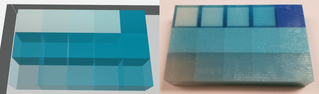
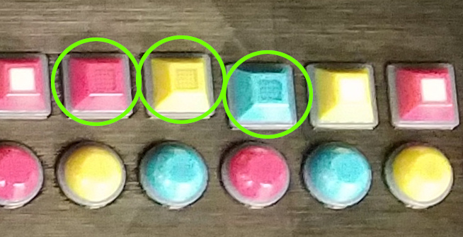
-The white centers only show up in some of the parts.
The white centers appear due to a default setting in GrabCAD Print. The parts have an outer shell that matches the color described in GrabCAD Print, but anything this outer shell doesn’t include gets turned into a white core. This is highly apparent on the Vero Vivid prints at the top, but can be seen when viewing the more opaque parts as well. The thickness of the outer shell is usually around 1mm thick, but can vary.
-None of the parts with “Translucent” or “Hollow” checked had a white core.
The white cores can be avoided by checking the “Translucent” box. This box does not make the part transparent. Rather, it makes the part print as a solid color. “Translucent” is automatically checked when “Hollow” is selected, so those parts also do not have a white core.
-None of the parts look hollow.
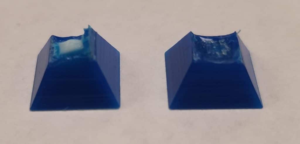
This was puzzling! Glancing at the pictures taken during the print, there was not a noticeable difference between the “Translucent” and “Hollow” parts. Opening one of the pyramid pieces that was supposed to be hollow resulted in a part filled with support material. The “Hollow” setting means that the internal volume is filled with support material. The word “Hollow” is just the descriptor that GrabCAD Print uses. This setting allows you to save on material usage by increasing support material usage. Below is a comparison of the white-core pyramid to the support-filled hollow pyramid.
Zooming in on the photos taken mid-print, the support material in the hollow parts is visible.
-The hemispheres on the left side of the tray have a different white center than the hemispheres on the right side.
This is not something easily understood, but it’s important to note that the blotchy white fill only appeared in the STL versions of the multi-body parts (which were on the left). The hemispheres on the right follow the same convention as the pyramids with white cores; when single parts are thick enough, a white core will appear internally. The blotchy pattern may have to do with the way the STL was created.
-None of the parts with the stepping pattern printed with white cores
This occurs due to the fact that GrabCAD Print sees each separate solid body slice as a different part. Each of these parts is not thick enough for the white center to show up. If these sliced parts were scaled up larger one would expect to find several small white centers in each of the slices.
Upon closer inspection of the parts, the Hex colored and PANTONE colored parts are slightly transparent, and the white core is slightly noticeable. This comes from the method polyjet machines use to create colors through blending various resins to create new colors. Since the Hex and PANTONE colored parts have Vivid Vero resins in their composition, some of the transparent properties end up in the parts. Here are a few of the hemispheres on a backlight. The purely VeroMagentaV part has the easily visible white core pattern (the pattern the multi-solid body STLs had).
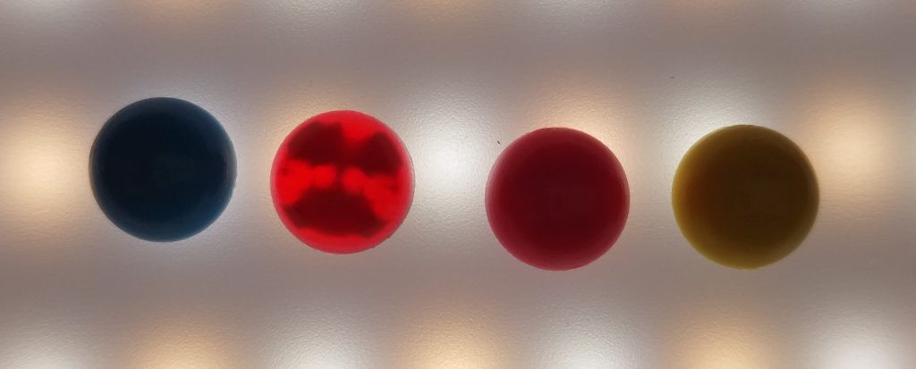
Under a stronger light the white core pattern in the “opaque” magenta hemisphere (second from the left in the picture above) is visible.
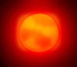
The pyramids also follow this pattern. Below is the opaque Hex colored magenta pyramid.
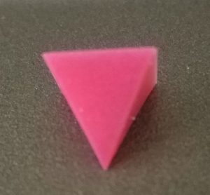
And now the same part underneath the stronger light.
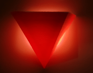
It is difficult to see, but with some arrows it’s a little easier.

Takeaways:
- Parts printed in Vero Vivid colors (especially VeroMagentaV and VeroYellowV) will print with a white core that does not appear in GrabCAD print unless printed with “Translucent” checked. These can even be noticed in the opaque colors depending on the ratio of Vivid resin used for the color. If the part is going to be studied carefully, it’s not a bad idea to check “Translucent”.
- Parts that are thin will not have the white core show up.
- The “Hollow” check box fills the solid with support material, even if the support material is entirely enclosed with a solid outer layer. This may not be easily visible in small parts during printing.
- To keep a purely glossy surface and save support material, keep parts as a single solid body. Otherwise the parts will have a stepping pattern created at the boundaries of the separate solid bodies.
Kelsey Gabel
Application Engineer
Computer Aided Technology, LLC