Calibrating Your F Series Printer
Stratasys are requiring a slightly different head calibration procedure than you might be used to with the F123 Series 3D printers(F120, F170, F270, F370). This procedure is now the standard for F series printers and should greatly reduce the message that sometimes pops up on the printer stating “No Material Detected At Head”.
Stratasys has begun requiring the manual calibration procedure be done prior to replacing a defective head as they have found that so many users were only performing the auto calibration.
This is also the only way the printer gets an accurate Z layer thickness reading as the Auto Calibration uses a sensor in the head to calculate the Z layer thickness.
Calibration Instructions
First, you will need to unload both model and support materials. Then make sure there is no build tray installed.
Now it is time to run the Auto-Calibration which takes a few minutes. The printer uses those plus shaped cut-outs on the back of the Z stage to get pretty close with the X and Y offsets.
Once the Auto-Calibration is complete you will then need to load both model and support material. Then install a new, unused build tray. At that point you will run the Manual Calibration by going through the commands on the printer screen. This will print out a grid pattern as shown on the graphic below onto your new build tray(and is the reason you need a new build tray to perform the calibration). Once the Manual Calibration part is complete, inspect the part. As your printout will be the grid pattern below, the red line will be a thin line of filament. Your printer will print in one color but referencing the graphic look for where the red line of filament is equal in distance from both of the thick blue walls. Find the correlating numbers on your grid as the X and Y values. The X and Y offset values need to be within 2 thousandths of Zero so you may need to run the Manual Calibration part more than one time. Simply use the sliders on the printers calibration screen and drag them to the appropriate value.
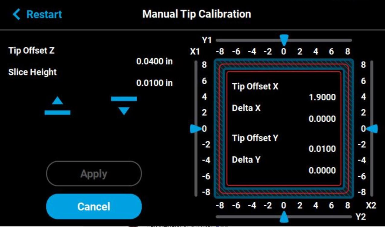
On the final Manual Calibration part only, take the Z measurement and enter that value. To get the right Z value you will need to peel off the top layer of the inner square of the calibration part. Measure the thickness of each side of that square in the middle, take the average of the 4 measurements and enter that value as the Tip Offset Z.
Now your printer is calibrated!
If you are having trouble and need additional assistance, feel free to reach out to us at CATI.
Ben Westendorf
Field Service Engineer
Computer Aided Technology, Inc.