How to reduce 3D print build time with Stratasys Insight Part 2
Using Contours to Save Time With Insight
In my previous blog we explored how to save 3D print time by increasing the size of interior toolpaths. While that tip is great for parts with large internal sections it doesn’t help when it comes to parts with lots of thinner walls. When a part consists of a thinner cross-section, the default toolpaths are a back and forth infill that can waste time and efficiency. This blog focuses on a new strategy to reduce build time for parts with thin cross-sections.
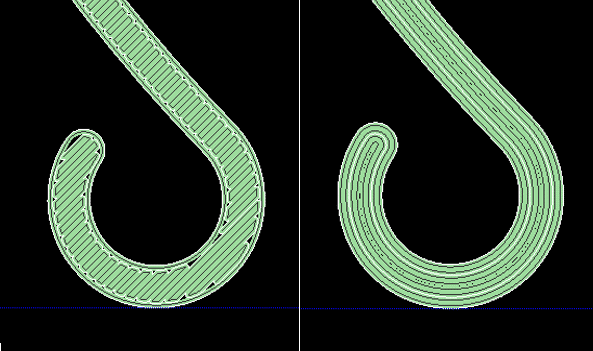
Parts with thinner walls typically consist of narrow and long cross-sections. As a result the machine prints an exterior wall contour and fills the narrow space between with a raster infill. The geometry restricts the printer’s speed by causing the rasters to be short, frequently change direction, resulting in increasing the build time. If these rasters can be avoided and replaced with continuous wall contours the build time often decreases by an appreciable amount, and reduces wear on the machine. There is a critical point where this tactic becomes slower, but that typically occurs with cross-sections with surfaces greater than 0.25” apart. The images below illustrate how parts are typically printed with no modifications to toolpaths and how changing the number of wall contours will change the toolpaths.
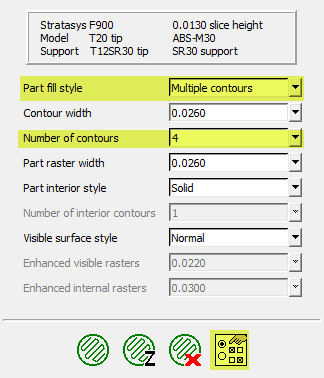
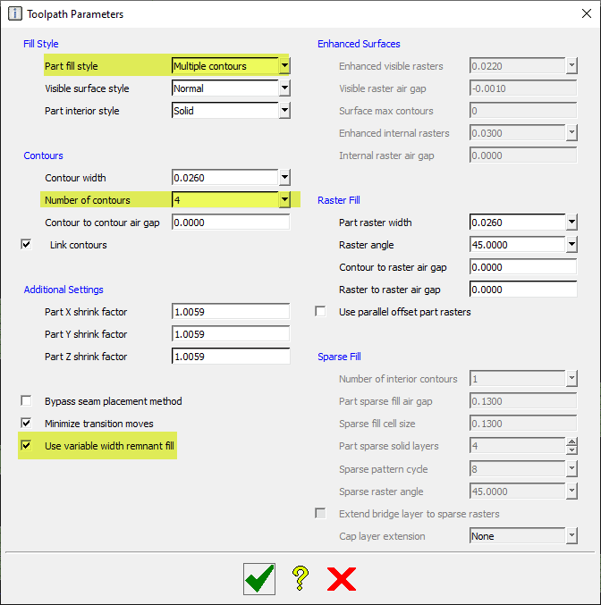
For those of you less familiar with the Insight software please refer back to my previous blog to catch up on some terminology and setting locations. The settings used for this tip can be found under “toolpath setup”. Simply change “Part fill style” to multiple contours and increase the number of counters until infill rasters are completely replaced with wall contours. Turning on variable width remnant fill can also be helpful to ensure a completely solid wall. This setting can be found by clicking the “Toolpath parameter” icon on the bottom right of the image bellow. In the toolpath parameter window the check box for “variable width remnant fill” can be found on the bottom left.
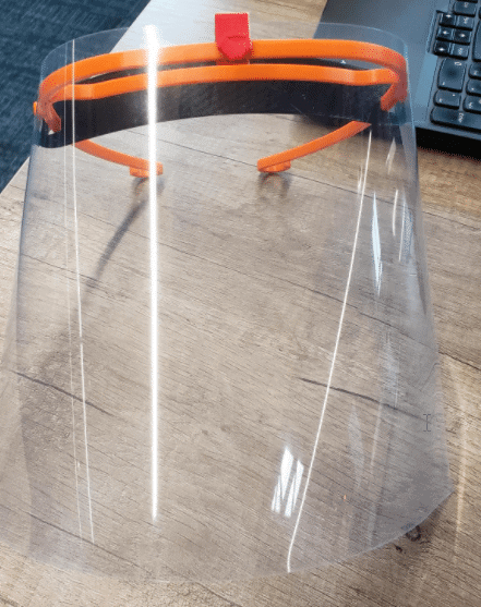
The file used for this blog is CATI’s Covid-19 face shield design and illustrates how to increase production capacity. Each face shield required 28 minutes of print time with the default setting and was reduced to 20 minutes using all wall contours. Taking it one step further increasing the layer height to 0.013” with all contours required only 14 minutes per part. This resulted in production capacity doubling, allowing CATI to donate more face shields to local first responders, hospitals, and other organizations.
Ryan Henigan
Manufacturing Solutions, Printed Parts
Computer Aided Technology, Inc.