7 Principles for Design for Additive Manufacturing (DfAM)
 3D printing started in the 1980s and since then quite a few different technologies have developed. DfAM (Design for Additive Manufacturing) will be applied differently to different 3D printing technologies. Different technologies require different optimization techniques which is important to keep in mind.
In this blog, we’re going to touch on PolyJet and FDM (Fused Deposition Modeling) technologies. Let’s take a look.
FDM Highlights
Stratasys has a large portfolio of FDM printers from the small but capable Mojo all the way to the F900 which is capable of printing 3’ x 2’ x 3’ – so there really is something available for everyone as far as material capabilities, build envelopes, and so on. One group of 3D printers I’d like to mention is the Stratasys F123 series, which is a group of well-rounded machines, which significantly improved throughput over the previous generation and has super simple to use GrabCAD Print software. GrabCAD Print software allows for native CAD file import (no more messing around with STL files) as well as many other benefits.
Materials
Some of the new materials available include the Nylon 12 Carbon Fiber which delivers the highest strength and stiffness-to-weight ratio of any Stratasys FDM material. It rivals aluminum as far as mechanical properties go and so we’re seeing a ton of applications where it is replacing metal parts.
The newest FDM material on the market is the Antero 800NA which is a PEKK-based FDM thermoplastic and is a high-performance material that is chemical resistant, possesses ultra-low outgassing properties, and exhibits high heat resistance making it well suited for aircraft and space applications.
PolyJet Highlights
One of the newest materials for the PolyJet line is called Agilus30, which is meant to simulate rubber material, so by its name and form it is a sturdy material but due to the fact that its PolyJet technology, rigid materials can be added to produce parts in a wide range of colors and Shore A values.
Vivid Colors have been added to the Stratasys J750 3D printer which brings the color capabilities to over 500,000.
Produce Results with Additive Manufacturing
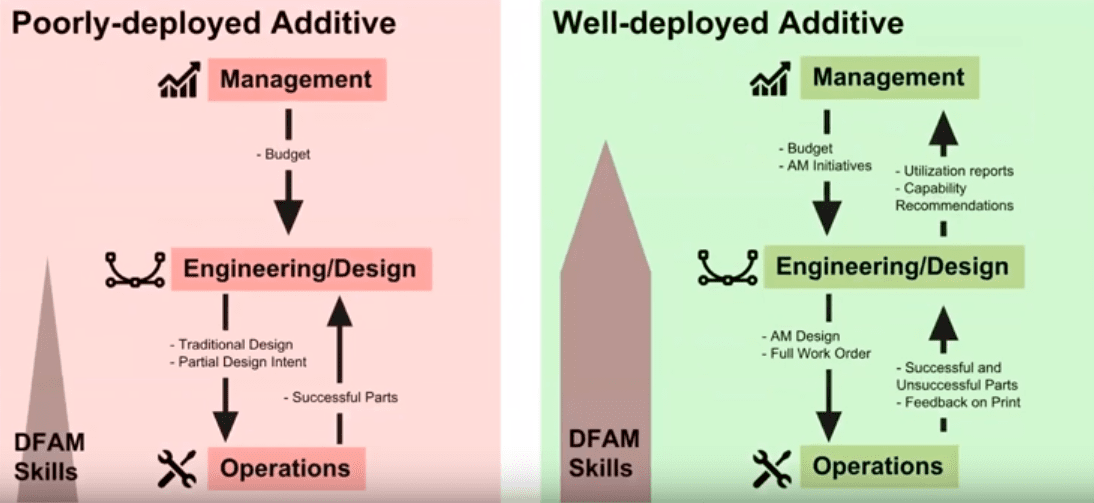
Additive manufacturing has the potential to be a revolutionary addition to your traditional manufacturing capabilities and can be implemented in two distinct ways: either very poorly, or very well. The path you choose will determine just how great of a tool it can be for you.
Poorly-deployed additive
Poorly-deployed additive is essentially just a replacement for traditional processes. So you’ll just take the existing parts that you currently design and then simply try to print them off. This is not very optimized and is a poor way to go out about it.
Well-deployed Additive
A well-deployed additive solution is thought of as a new tool for improving manufacturing aid functionality and cost.
There really needs to be a two-way street for DfAM to work properly. One common example we see is that management sets a budget for engineering to get them the equipment and to start printing parts. This normally doesn’t go well because essentially there’s no optimization or feedback. A well-deployed additive will have a two-way street going all the way from management to operations and then all the way back. This is the type of workflow you want to develop in your organization to make sure that Design for Additive Manufacturing is optimized well.
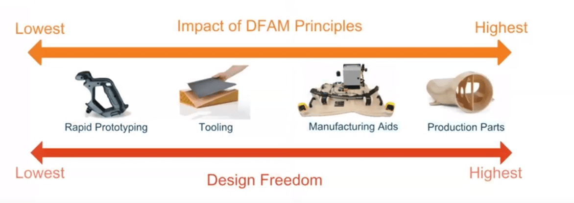
What does DfAM mean?
Let’s clarify what Design for Additive Manufacturing means and where the benefits really lie. The impact itself is highest for production parts and lowest for rapid prototypes. If you’re spending engineering time to optimize a rapid prototype, one that you may only print just one or two of, the cost and benefit may not be significant enough to justify the time spend to optimize it. On the flip side, if you’re printing batches of printed parts the time spend optimizing will pay dividends when the material time savings are multiplied throughout the whole batch.
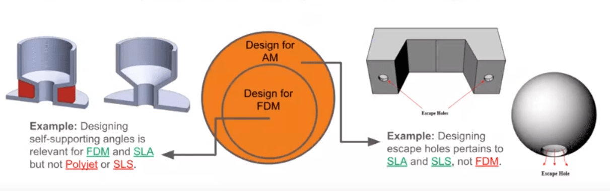
Just to reiterate something that I mentioned earlier, different additive manufacturing technologies require different types of DfAM optimization. In the image below, the model on the left, if printed on FDM or SLA technology, could yield significant material and time savings if the bottom angle of the cuff feature was just changed 5 or 10 degrees.
For the model on the right, when printing in SLA or SLS technologies, providing escape holes in a hollow model reduces material usage drastically, while in FDM it would yield no benefits at all.
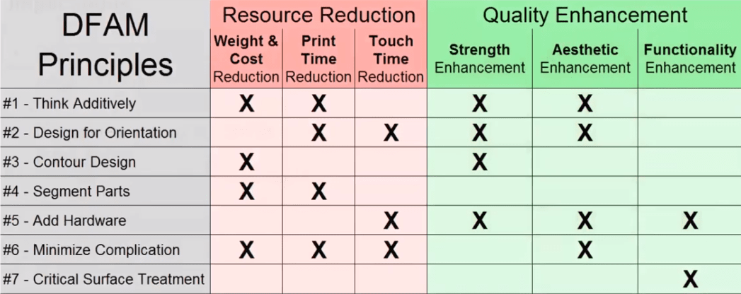
The Principles of DfAM
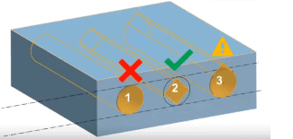
#1. Think Additively
Most engineers today think “subtractively” because traditional manufacturing generally means taking a block of material and removing material from it. So now we need to take that idea and flip it on its head because now the less material we use, the less cost and more time we save. It’s a different thought process as far as manufacturing goes. In the clip below you can see a few use case scenarios of this.
In summary, well-deployed DfAM requires not only skill but a new mindset. Again, it’s really flipping from subtractive manufacturing to additive manufacturing.
#2. Design for Orientation.
How you place a part on the printing bed will lead to some differences when it comes to your final part. For instance, if your part is laying on its side, it will give it great strength and accuracy, however, if it’s laid flat it will yield the fastest print, and if you print it standing up, it will have the best appearance but will be the weakest part.
Design for orientation requires maximum communication between engineering an operations. Operations are the people running the printers who will know what angle is self-supporting or not self-supporting and they will need to have communication with the engineering department.
#3. Contour Design
Contour designs mean that certain parts can be printed with just one or two extrusion lines. With those extrusion lines, you can create some really lightweight but strong parts such as wing features.
#4. Segment and Bond Parts
What if you have a part that is too big to print? Some people think they have to come up with another manufacturing method, however, we can simply just segment the parts by cutting the part into whatever sections will fit in the printer and then bond them together. A tip you can do with that is to use dovetail joints (there are different softwares that can help with that) and the dovetail joints will make sure that you have strongest cut and joint.
There are benefits of segmenting parts that do fit entirely in the printer. However, if a couple of portions of the part were segmented away and printed separately significant time and material savings can be had.
Note: You have to make sure that this does not become a traditional type of design for assembly process. I’ve often seen customers segment parts almost to an extreme and some of the benefits are actually negated. So just be aware that as you’re doing that kind of segmentation, that you don’t go overboard.
#5. Add Hardware
There are many different types of hardware that can be added. For example, if you have hot or abrasive issues with parts you can add bushings to those particular areas that are having contact issues.
If you’re trying to do threading, I personally recommend not printing them because there are better ways to go about it. One of those ways is to go with heated inserts or Heli-Coils so that way you can have metal threads in your 3D printed part and it will be great for long-term use.
If you have any sort of magnets, rods, or other fixtures you want to put into a part, there are always some quick ways to put in some locating features in there so you can quickly snap and glue it in.
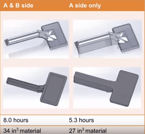
#6. Minimize Complications
This principle is a little interesting because it kind of goes against the original idea of “the less material we have the better.” If you’re printing with FDM technology that requires support material and you have a part like the one pictured below, that handle part will have support material throughout it. Support material adds significant time to the printing process because every layer in the model needs to switch from model to support, but if we eliminate the support material we can actually increase our print time significantly.
To see a real-world example of this, check out the video clip below.
So if you’re trying to improve a part or if you’re having issues printing a part don’t print the whole part if you don’t have to. Iterate only the portions of the part you’re having problems with, for example, if you’re having a locking portion of a part break off and that’s the only portion that’s having issues, don’t keep reprinting that part over and over again just work on the tab features and the proper orientation.
#7. Critical Surface Treatment
In the video example above, I demonstrate three ways to go about holes depending on the situation. If you’re printing with FDM technology, usually, by default printers will print one or two perimeters around the hole and it will kind of raster fill the surrounding areas. If you plan on reaming the hole, it’s great to add some extra contours to those holes so there’s actually more solid material.
For example, if you print a part that has a very light and sparse interior and you only have one or two contours, if you ream into those contours you’ll actually go into those hollow air gaps inside the part so you’ll reduce the structural rigidity of the part significantly.
In summary, these principles offer different benefits for different fields, so based on whatever field you’re trying to improve you can go ahead and take a look at that specific principle.
Want to learn more about designing for additive manufacturing? The recorded webcast below focuses specifically on FDM.
Related Articles
Jigs and Fixtures: Changing the Factory Floor with 3D Printing
3D Printing Support Material Removal and Surface Finishing Hardware
What to Look for in a 3D Printer: The Best 3D Printer by Industry
About the Author
 Simon Indrele is a 3D Printing Application Engineer based out of Philadelphia, Pennsylvania and has been part of the Fisher Unitech family since 2017. Simon has over 13 years of experience in the 3D printing industry and has spent most of his career in production and application engineering. As well as being Stratasys Certified, Simon specializes in 3D scanning and reverse engineering.