Creating Prototypes with Overmolding Using Polyjet 3D Printing
Have you ever questioned the integrity of a screwdriver after just glancing at it? Or wondered how quickly a drill’s battery pack would drain before ever pulling the trigger? Does the appearance or feel of a product tell you anything about its quality?
If you’ve ever found yourself doubting a certain product before touching it, you’ll understand that – yes, there’s often a lot to be learned from just the look and feel of products! Small design details go a long way in communicating sturdy materials and quality engineering to end customers.
With PolyJet multi-material 3D printing, you can ensure these design choices can be incorporated into your products from the earliest stages of the design cycle – starting with your very first prototype! This allows refinement and natural evolution of your designs based on real physical experience – not just intuitive judgement calls informed by technical drawing and CAD renders.
Overmolding is a simple feature that elevates the look and feel of your product. PolyJet 3D printing makes it simple to produce realistic looking and feeling rubberized grips with only a few additional steps. In this blog we’ll take a look at the overmolded prototyping process start-to-finish to show you how PolyJet can accelerate your design cycle.
In this blog I will be using SOLIDWORKS for my 3D modeling, but any CAD package that support multi-body modeling should be able to follow the same steps with minimal differences!
1. Start by Modeling the Base Body
This is the basic form you plan to add your overmolding to. I will be using the blue handles of these pliers. I like to visualize my CAD plans, so I also sketched a quick preview of what I want my grips to look like.

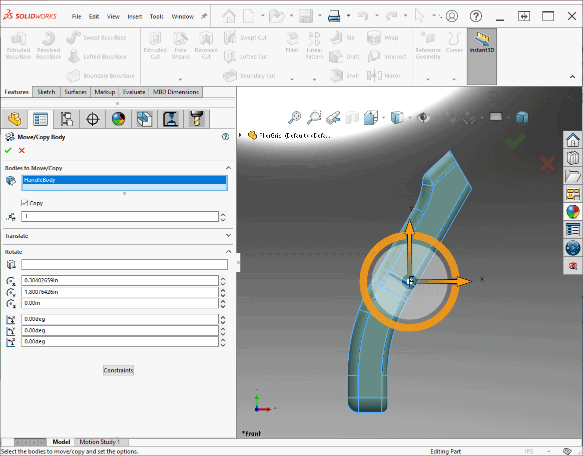
2. Open the Part File and Create a Duplicate of the Body
Use the Move/Copy tool. Don’t apply a rotation or translation, we want it to remain in exactly the same spot! Overmolded features match the shape and curvature of the base tool body, so rather than remake it, we’ll just copy our existing geometry.
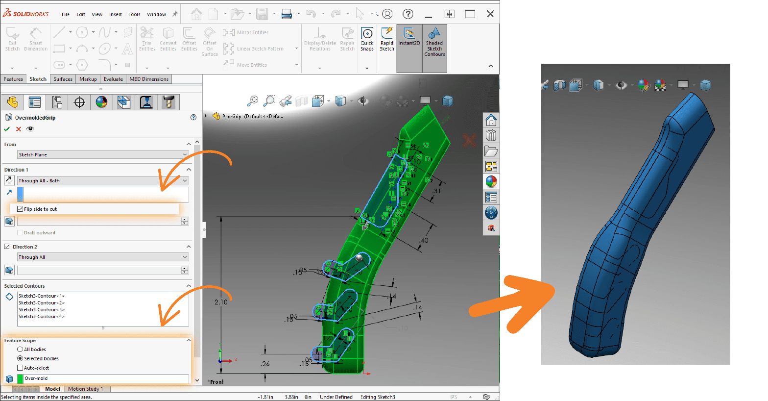
3. Create a Sketch and Cut-Extrude the Shapes You’d Like Your Overmolded Addition to be
Use the Flip side to cut option to keep only the common areas of your extrusions. Then use the Feature scope section to ensure you only cut your duplicate body. You should now have multiple bodies that overlap with the original base body.
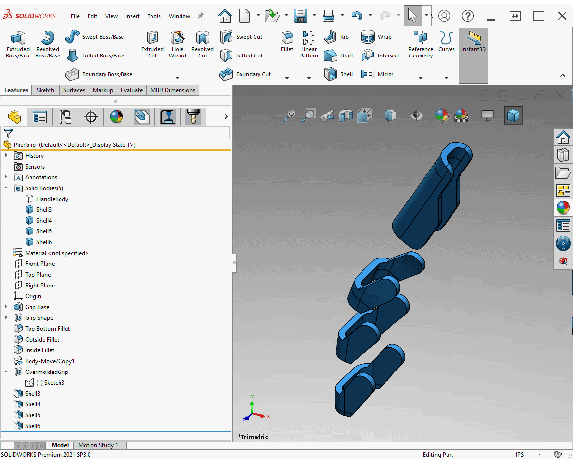
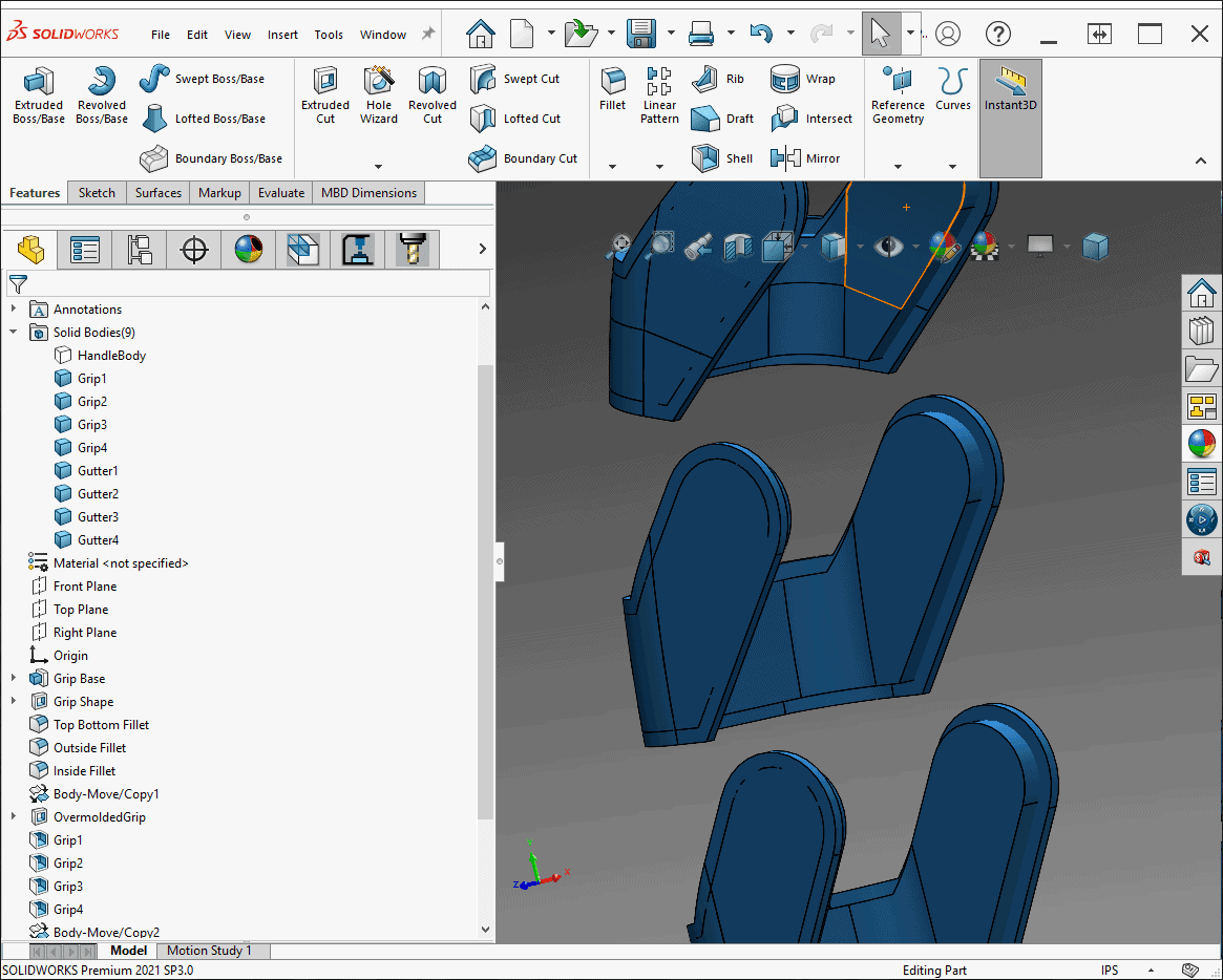
4. Use the Shell Command to Create a Thin Outer Shell for Each of the New Bodies
This will be the depth of your overmold. I chose to use a thickness of 0.06”. After this step, you’re done! Import the multi-body part file into GrabCAD and use the part prioritization tool to make sure your grips are printed embedded into the handle. However…
Most overmolded features a gutter, a shallow recess that surrounds the rubberized grips. It’s used during the injection-molding manufacturing process, so it’s not strictly necessary when 3D printing. Nonetheless, adding it will give our product just another little bit of realism! Continue to Step 5 if you want to follow along, otherwise, skip to Step 9 to print now.
5. Use the Move/Copy too to Make Another Duplicate of Your Base Body
As before, don’t apply any rotation or translation.
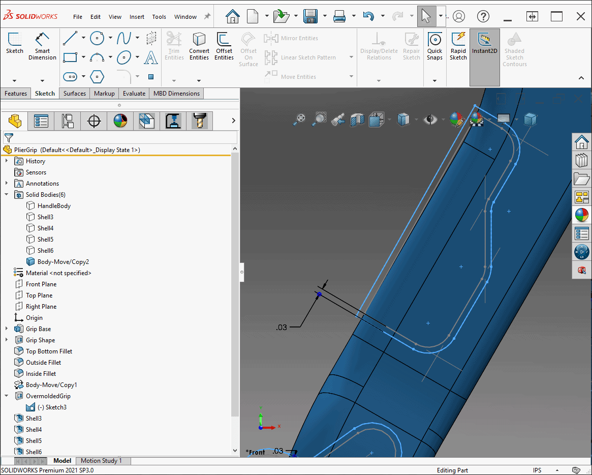
6. Create a New Sketch Based on Your Original Grip Design and Offset the Contours Slightly
The offset value I chose was 0.02”.
7. Repeat Steps 3 and 4 with the New Sketch, this Time Choosing a Thinner Thickness Value for the Shell Operation
I chose 0.02” for my shell thickness value. When you finish, you should have 2 sets over overlapping shells – one that will become the rubberized grip, and a thinner one that will become the gutter around it.
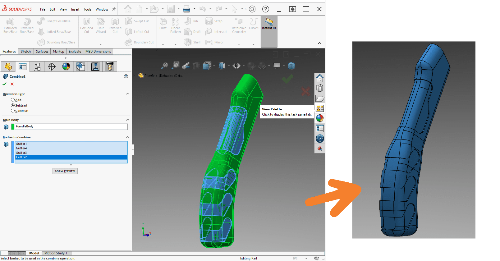
8. Subtract the Gutter Bodies from Your Base Body Using the Combine Tool
Because the gutter body will eventually become a lack of material, we need to subtract it from the main body before sending our part to be 3D printed.
9. Turn on Visibility of the Grip and Handle Bodies and Save Your Work
Your overmolded grips are ready to be printed! If you’re working in Solidworks, Inventor, Creo or any other CAD packages GrabCAD natively supports, you don’t even need to export your work. Simply drag and drop your part or assembly into the GrabCAD window to import it.
Find a full list of GrabCAD supported programs and file types here!
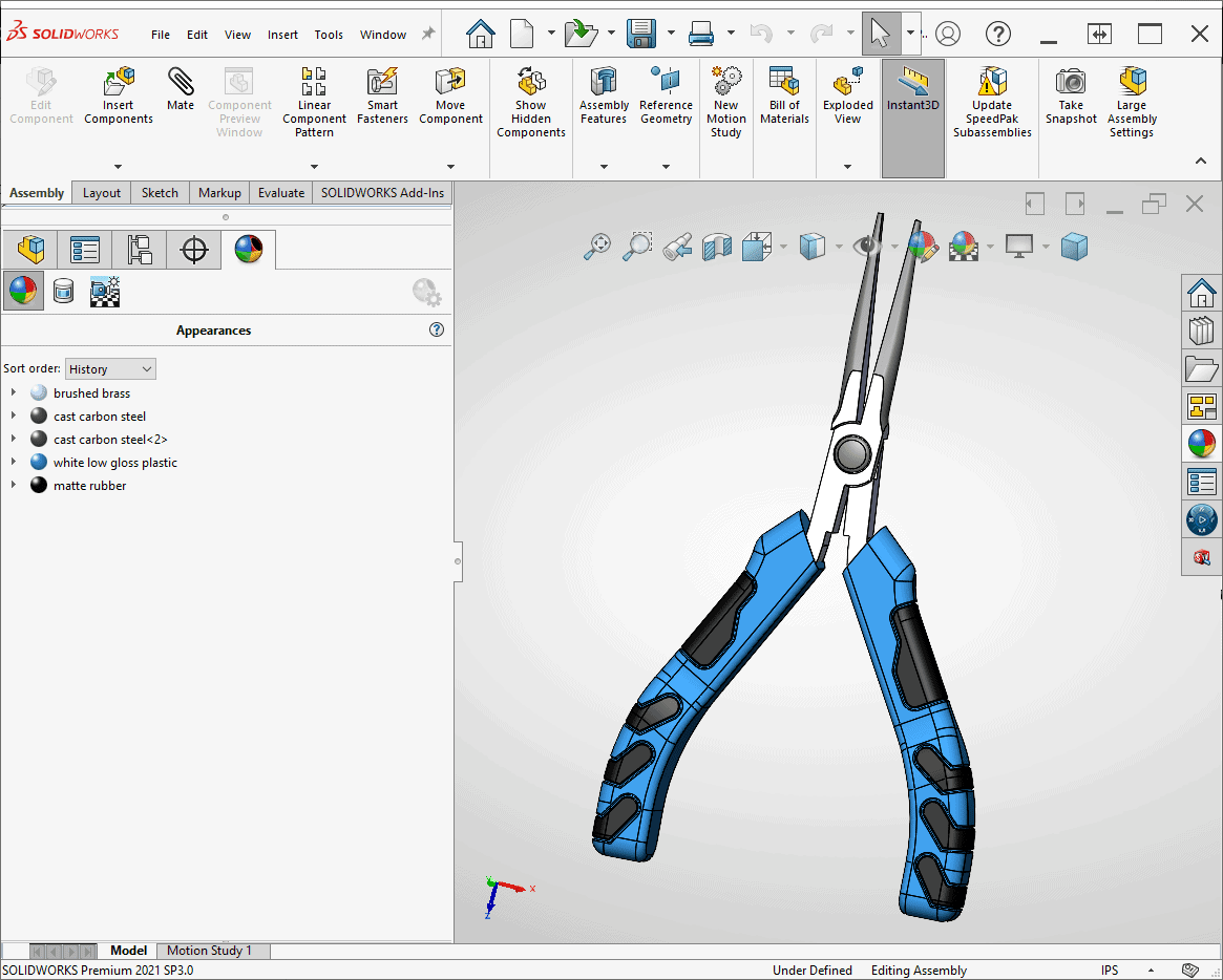
For my assembly, I also added some color and small fillets to break the edges of the new additions. For non-rubberized components, you can assign colors in SOLIDWORKS, however, the export process can be unpredictable and sometimes colors may not come out as you expect. I plan to use the SOLIDWORKS exported color on the metal jaws of my pliers, but I’ll assign colors and materials in GrabCAD for everything else.
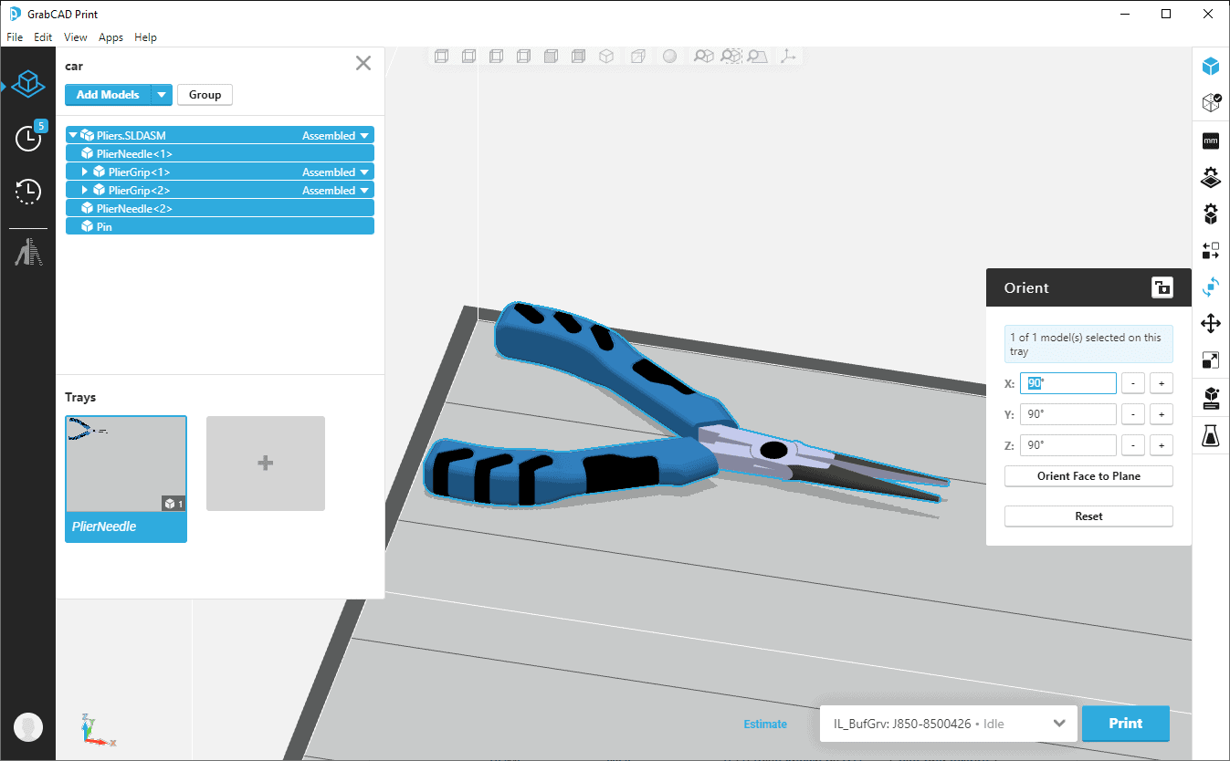
10. Drag and Drop Your Part or Assembly into GrabCAD Print and Choose Your PolyJet Printer
Then, select the top level group in GrabCAD’s part browser in the top left corner and use GrabCAD’s orientation tools to arrange your part on the tray as you’d like them printed. If you import an assembly, GrabCAD will faithfully recreate the location and orientation of all parts.
11. Select Model Settings and Use the Parts Browser to Select Each Body Representing Your Overmolded Parts
In Model Settings, click the drop-down menu and choose the Digital Materials tab. Select your rubber-like material (either Agilus or Elastico depending on your printer) and one other rigid Vero material.
The space below the Combine Materials panel will populate with a selection of material combinations. Hovering over each one will give you a description of its material properties. To choose a material, simply click on whichever option best suits your application. I chose a Shore-A 70 equivalent material for my grips.
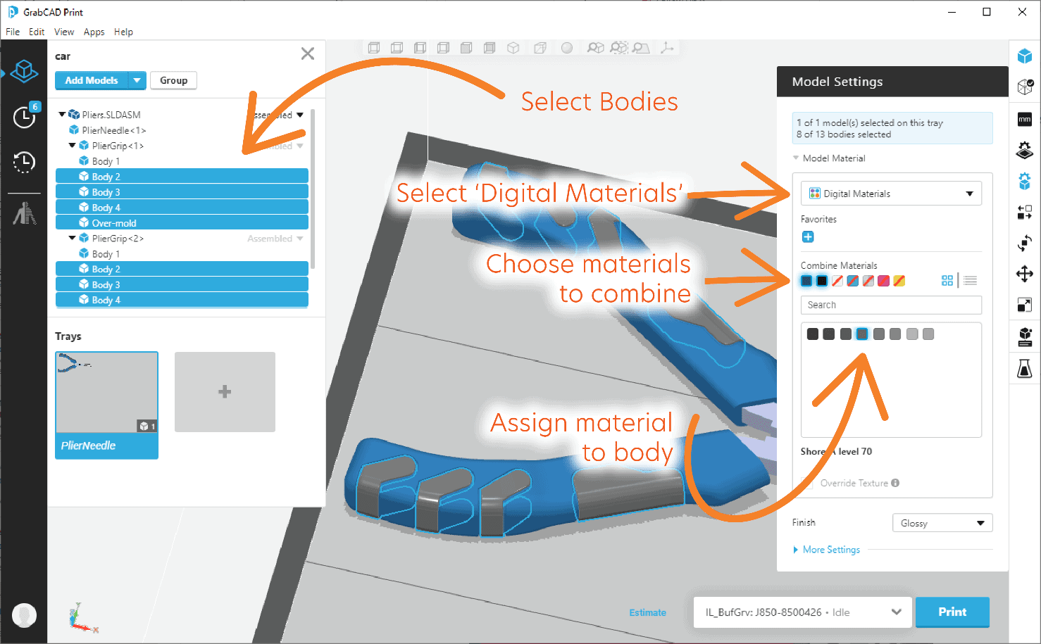
12. Select and Assign Materials to the Remaining Bodies on Your Tray
You can use the same method shown before, select from tray materials or use the color picker, depending on how you want you model to look and feel.
If you select a material or color in GrabCAD, it will print in only the material or color you selected, producing a very clean look. If you leave bodies as they were exported from SOLIDWORKS, GrabCAD will print the with whatever color is already applied to them. In my case, I opted to leave the metal pieces of my pliers as they were exported from GrabCAD. Your mileage may vary using this method! Engineering CAD programs can have varied results when exporting color textured bodies.
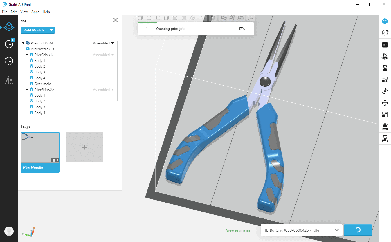
All that’s left now is to print your prototype!
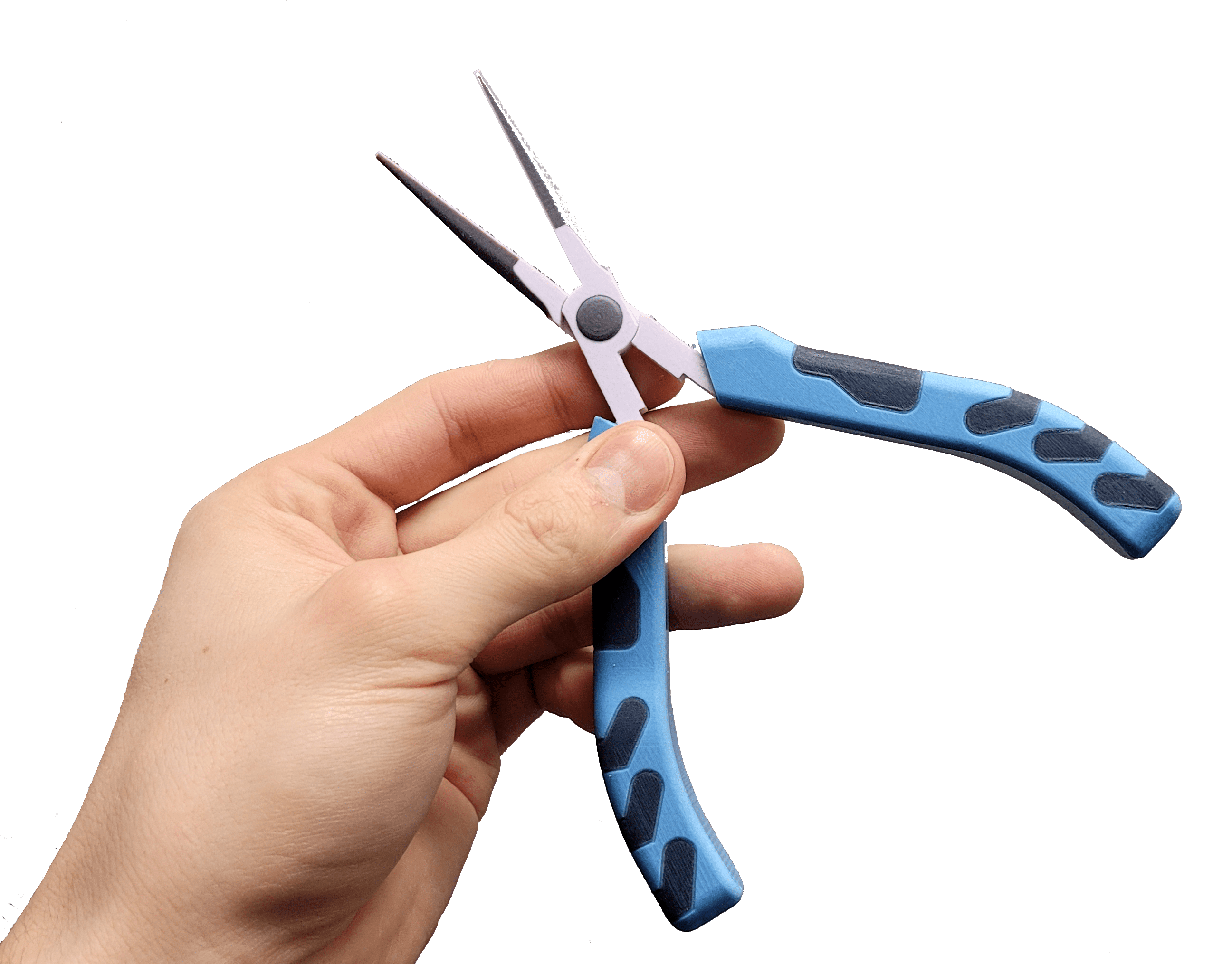
Here’s how my finished product turned out! The black grips are rubberized and feel like true overmolded components.
I hope this blog was informative and you might be inspired to apply this technique or others like it to your current design process!
For any questions regarding 3D printing, GrabCAD, SOLIDWORKS or any of the topics mentioned here, please feel free to reach out to us at sales@cati.com or 888-308-2284.
Jake Wenzel
Applications Engineer, Manufacturing Solutions
Computer Aided Technology