Discovering your 3D Printer’s Capabilities – Part 3
This is the last of a brief series on understanding the capabilities and limitations of your 3D Printer. When you know what your machine can achieve, it can be applied to significantly aid your part design as well as throughput and quality.
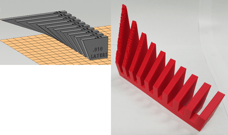
In part 1 of this series, we discussed how structural supports are dependent on 3 variables; technology, material and layer thickness. We showed how some overhangs can be built in FDM without a support structure.
See Discovering your 3D Printer’s Capabilities – Part 1.
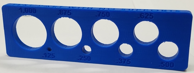
In part 2 of this series we looked at how FDM supports holes in the horizontal orientation. A horizontal hole, with the axis parallel with the build platform, is sliced into layers with half of the hole creating overhanging layers.
See Discovering your 3D Printer’s Capabilities – Part 2
Now, that we understand some of the capabilities and limitations, we can incorporate these techniques into the design of a 3D printed part.
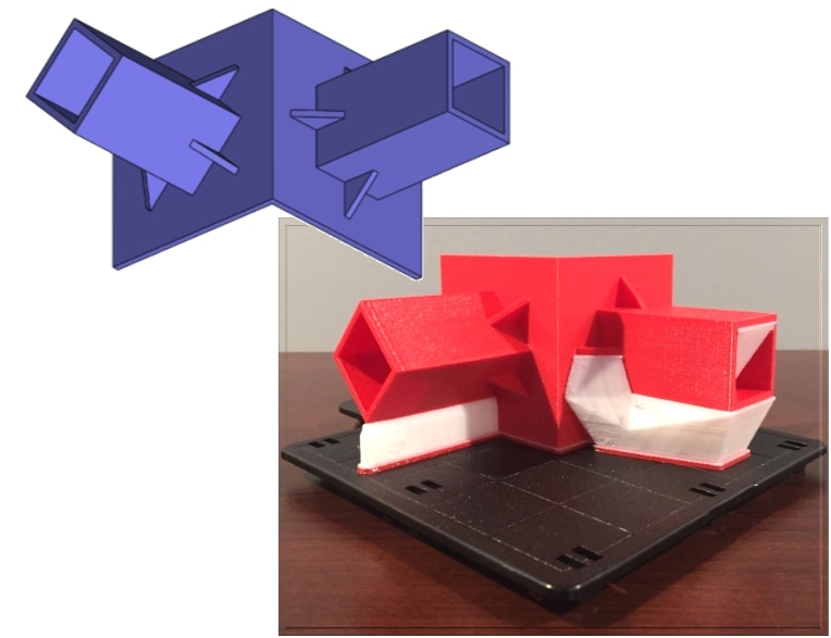
The mechanical part shown below is an end of arm vacuum fixture for robotic tooling. The square channel shields a bundle of wires and tubing. By changing the orientation of the shield design by 45 degrees (based on lessons learned in part 1 of this series) note the significant amount of supports that are eliminated on the left side compared to the right side. This design change will also reduce build time, material cost and labor cost.
Computer Aided Technologies, LLC offers Advanced Insight training with Stratasys certified trainers to help customers get the most from their 3D Printers. For information please contact your CATI sales representative or call CATI at 888-308-2284.
Mark Abshire
Application Engineer, Additive Manufacturing
Computer Aided Technology