Stratasys FDM Printer Routine Maintenance
Stratasys FDM Printer Routine Maintenance
In order to keep your Stratasys FDM printer running smoothly there are some routine maintenance procedures that must be done.
Here are some steps you can take to keep your printer working properly.
Daily Maintenance
Purge Bucket
On a daily basis you should empty the purge bucket. The F123 Series printers do not have a purge bucket so cleaning out or vacuuming the chamber will remove all the purge material from the printer.
I will address the F123 Series printers at the end of this blog because they are a little different than the other printers.
The purge bucket is located in the rear of the build chamber. To remove it simply lift up and then remove it from the printer. Empty the purge bucket and then reinstall it into the printer.
 Tip Wipe Assembly/Brush Flicker Assembly
You should inspect the tip wipe assembly after each build to make sure there is no material build up on it or excessive wear.
Material build up on the tip wipe assembly or a worn out tip wipe assembly can cause part quality issues.
To replace the tip wipe assembly lift it up and out of the printer and then install the new tip wipe assembly.
 Tip Shrouds or Tip Shields
You should inspect the tip shields after each build for damage or material build up.
You can clean the material off of the shields using a wire brush.
If the material will not come off or the shield is damaged in any way replace the tip shields.
To replace the tip shields
Enter Head Maintenance.
a. From the display panel press Maintenance.
b. Press Machine.
c. Press Head. The head will come to rest in the center of the chamber and the Z platform will change position.
Remove the head cover by pressing the tabs in and pulling it away from the head. The tabs are located on the sides of the head cover as shown below.
Depending on your specific printer you may have round tip shields or square tip shields but the tips shields are all replaced the same way.
To remove the tip shields position the blade of a small screwdriver between the tip shield and tip plate. Use the blade of
the small screwdriver to separate the tip shield from the tip plate.See the picture below for reference.
Clean the tips with a wire brush.
To install the new shields align the end of the tip with the tip shield opening and push up on the tip shield to install it.
If you have the square shields make sure you put the edge with the slots towards the back of the printer as in the picture below.
Also make sure the tip shields are flush with the tip plate.
The one on the left below is not fully installed.
Reinstall the head cover.
Recommended at 500 Hours
Fan Filter, Brush Flicker Assembly, Tip Shrouds
See the Brush Flicker Assembly and Tip Shrouds Maintenance/Replacement procedures above.
Clean the fan filter
Locate the lower fan on the rear panel of the printer and remove the plastic frame (snaps on
and off) that secures the fan filter.
Clean the filter with soap and water, and blot it dry.
Reassemble
As needed maintenance
Remove debris buildup
Remove all material buildup on the Z platform and around the lead screw. Failure to do so could cause the base to not be level or the Z platform to jam at its upper limit.
Vacuum the build chamber
Vacuum the build chamber to remove debris and all purged material from the printer.
Clean the door
Clean the door with glass cleaner.
Tip area clean up
Material can build up on the metal strip behind the extrusion tips. Build up can be caused by an overflowing Purge Bucket or an improperly adjusted Tip Cleaning Assembly.
From the display panel, press Maintenance.
Press Machine.
Press Head. The head will come to rest in the center of the chamber and the Z Platform will change position.
Clean the area of all material (see picture below) using the needle nose pliers supplied with your Start Up Kit
Press Done, until back at Idle.

Chamber Light
Replace Chamber Light when it goes out.
2000 Hour Maintenance
Liquefier Tip Replacement
Replace Tips at approximately 2000 hours – depending upon operating conditions. Tips can also
be damaged by improper care while performing maintenance in the area around the tips.
Removing Tips:
1. You will need to make sure the printer is powered ON before replacing the extrusion tips.
2. From the display panel press Maintenance.
3. Press Machine.
4. Press Tip.
5. Press Replace.
6. The printer will display Load Model – Unloading.
7. You can now open the printer door and replace the tips – or you can cancel the tip
replacement procedure.
8. Remove plastic head cover by squeezing raised pads on sides of cover and then pulling the cover off the head.

9 Use 7⁄64” T-Handle Allen wrench to loosen the heater block screws three to four full turns counterclockwise – or until the top of the screws are flush with the metal cover. DO
NOT remove the screws entirely. The screws are highlighted in red below.

Use needle nose pliers to grasp the stainless steel shield of the tip.
Pull the tip shield toward you, then pull down to remove the tip from the heater block.
Discard the used tip.

Repeat for second tip
Installing Tips:
1. For a Dimension BST1200es, the SUPPORT tip and MODEL tip are interchangeable. Both tips are the same as the MODEL tip shown below (The tips come in a Red capped
container).

2. For a Dimension SST 1200es, you must identify the correct replacement tip. The SST 1200es uses two tip types. You must make sure a SUPPORT tip is used on the LEFT side of the head
assembly. A MODEL tip must be used on the RIGHT side of the head assembly. The Model tip comes in a red capped container. The Support tip comes in a black
capped container.
3. With gloved hand, insert the new tip into the heater block.
4. Use needle nose pliers to grasp the stainless steel shield of the tip.
5. Pull the tip shield toward you, then lift up to install the tip.
6. Push the tip toward the back of the printer once it is all the way up against the heater block.
7. Verify the tip is fully inserted into the heater block and that the stainless steel shield is aligned.
Correct Incorrect


Incorrect
8. Use 7⁄64” T-Handle Allen wrench to firmly tighten the heater block clamp screws.
9. Repeat steps 3 through 8 for second tip if necessary.
Note: Make sure Tip remains all the way up against the heater block as you tighten the screws.
10. Install the tip shrouds by pushing up onto the tips.
11. Replace Plastic Head Cover and close the printer door.
12. The printer will display Tip Maintenance – Tips Replaced? – select Yes to begin material load.
a. The printer will display Load Model – Replace Both Cartridges (flashing).
• If you want to replace a material cartridge, do so now
• If you do NOT want to change a material cartridge, you must unlatch and latch the
cartridges to continue (Press the cartridge forward to unlatch, then press it forward again to latch).
The printer now begins to load material.
After Material Loading is complete the printer will display Tip Calibration – Install Modeling Base And Build Calibration Part.
Make sure a NEW, UNUSED modeling base is installed before starting calibration.
Tip Calibration
Tip replacement requires calibration.
Select Start Part (flashing) – the printer will run two calibration parts.
• The printer will automatically build a Z Calibration part, measure the part and calibrate
the Z Axis for tip depth and tip level (approximately 5 minutes). The Z calibration is
automatic.
• The printer will then automatically build an XY Calibration part (approximately 10
minutes). You must inspect the XY Calibration part and calibrate the X and Y axis for tip
offset:
When the XY Calibration part is complete the printer will display Remove Part and Select XY Adjustment
Remove the xy calibration part from the printer.

Using the magnifier sent in the start up kit check the -x and +x lines and locate where the Support road is most centered between the two lines of Model material.
If the number is on the negative side it will be a – number and a + number for the positive side. Select increment for a + number and decrement for a -.number.
In the example above you would increment to +2. This is where the support material is most centered.
After incrementing to +2 press select Y and do the same procedure there. In the example above the support is most centered at -4 so you would press decrement until you get to -4.
Select done.
The printer will return to Maintenance. Run the x y calibration again to verify results.
Once completed press done until back at Idle.
F123 Series Maintenance Schedule
The recommended Maintenance procedures for the F123 Series Printers are listed below.
Weekly
Clean the build chamber and remove all purged material from the printer.
Clean the platen.Carefully remove purged material debris that have fallen into the openings of the platen.
Monthly
Clean/inspect tip wipe assemblies.
Replace if worn.
To remove lift the tip wipe assembly up off of the post and then replace it with a new one.

As needed
Clean the exterior surface of the printer with a damp cloth.
Clean the touchscreen with the cleaner supplied in the welcome kit and a microfiber cloth.
1500 Hours
REPLACING A HEAD
When a head reaches 1500 build hours a warning will be displayed on the User Interface and
the Head Status Icon will be highlighted in red on the Materials page. You can continue using a head
which has exceeded its odometer limit, but it is highly recommended that you change the head as part quality
will be unpredictable.
REPLACING A STANDARD HEAD
1. Unload material from the head that will be replaced
2. With the printer powered ON, open the top cover
3. Depress the release tab and unclip the head ribbon cable for the head that will be replaced
(model head is on the left, support head is on the right).
4. Disconnect the material tube for the head that will be replaced.
5. Unlock the head release lever for the head that will be replaced.

Pull the head assembly out of its position within the gantry and remove it from the printer.
Insert the new head. Lock it in place. Attach material tube. Plug in cable. Close the cover.
An automatic calibration will be automatically preformed prior to starting the next build.
You need to run a manual calibration after the automatic calibration is complete.
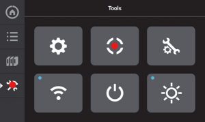
To run the manual calibration press the Tools Icon and then press the Calibration Icon.
They are highlighted in red below.
Press Tip Calibration
Click on Start under Manual Tip Calibration
REPLACING A PLA HEAD
Replacing a PLA head is a bit different because there is no Support Head.
The PLA head is installed on the Model side (left). It prints both Model and Support material and a cooling module is installed on the right (support) side…
They are still replaced the same way as a standard head however a calibration is not performed when replacing a PLA head since there is no Support head installed.