Get Snappy with Snap Hook Fastening Feature in SOLIDWORKS
Hello again everyone! Have you ever wanted or needed a method for a 3D printed project that could be disassembled and reassembled without adding screws, nuts, or threaded fasteners? An enclosure for example? I am sure the answer is “Yes.” Have you considered using a snap hook feature in your design to accomplish this task? Was your next thought that you weren’t sure how to design it or where to begin? Let me make things a little easier for you to get started. SOLIDWORKS has Feature commands called Snap Hook and Snap Hook Groove for just such a purpose. They fall into the family of design known as Snap-Fit joints.
Snap-Fit joints are extremely common when it comes to plastic components and there is quite a bit of engineering that goes into getting those connections perfect (Except for the ones that aren’t and break on us early. That is a different story and outside of our scope.). There are of course times when we need speed and efficiency over perfection. We want something that is functional and easy to implement. Especially if we are planning on 3D Printing our design and iterating quickly. This is where the Snap Hook and Snap Hook Groove commands come into play. These commands built into SOLIDWORKS are a wonderful place to start but they do not include all the options we may want for complete design control of the Snap Hook and Snap Hook Groove. With that said, they still work well and do not require a lot of background knowledge in snap-fit joints for us to implement them.
Let us look at a simple example to apply a Snap Hook feature. In the image below you will see that I have the bottom half of an enclosure that has been created. The DesignTree consists of an Extruded Boss, a Fillet, and a Shell.
![]()
Next, I Mirrored the body. This now gives us both halves of the enclosure.
![]()
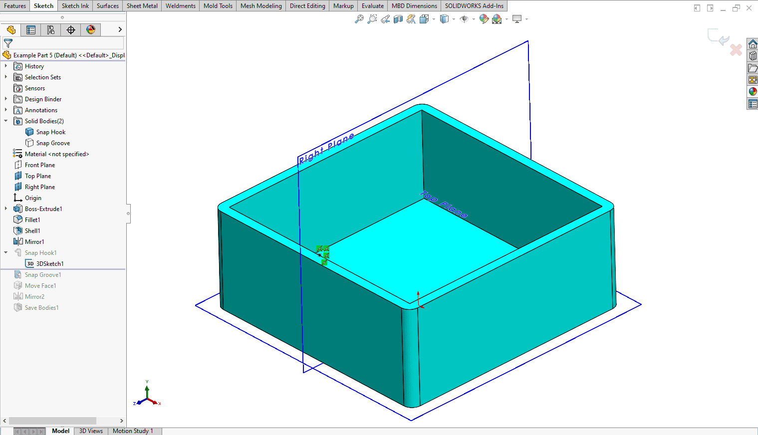
For the next few steps, it is easier if you hide the top body. The Snap Hook feature creates a 3D Sketch and is required to properly place the Snap Hook feature. I recommend creating your 3D Sketch first and then selecting it once you have activated the Snap Hook command. The Snap Hook command requires a single sketch point for the feature. The Snap Hook feature does require that you select a plane for locating the sketch point in the 3D Sketch, otherwise you may get a warning. This plane can be a face on the part or a plane. I activated a 3D Sketch and then chose the top face of the bottom body for my 3D Sketch. I then activated my sketch point command and placed a point on this face. Then I added relationships to fully define the sketch. The point is located on the midpoint of the interior edge of the lower enclosure body. Then I exited the 3D Sketch.
You can see that my midpoint falls along the Right Plane of my part.
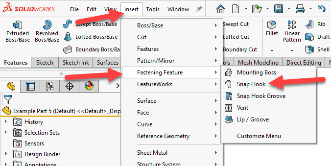
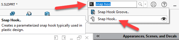
Now it is time to activate the Snap Hook command. There are a few ways of doing this. We can go to our dropdown menus and select Insert, Fastening Feature, Snap Hook. We could also use our search command tool and activate it. We can also add the Fastening Feature toolbar and activate it from there.
Dropdown menu (below)
Command Search (below)
Toolbar (below)

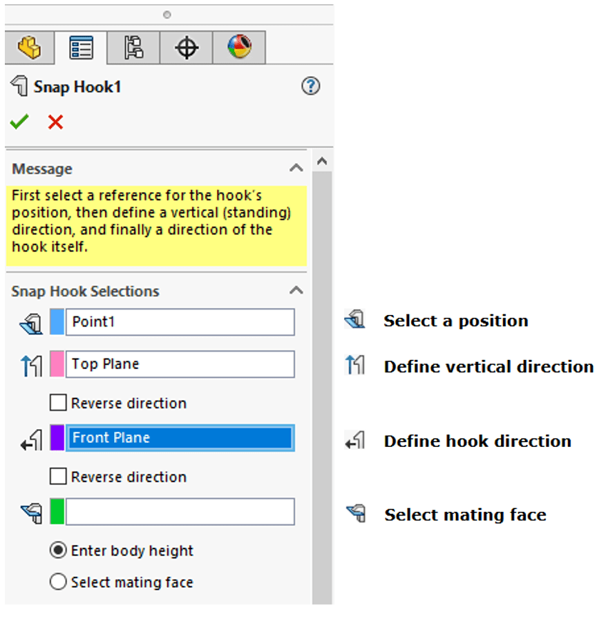
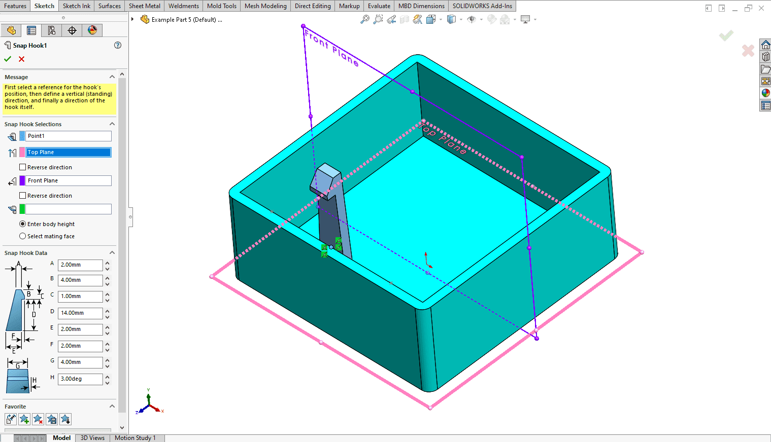
Once the Snap Hook command is activated, we will need to fill in some information under the Snap Hook Selections area of our Property Manager. For clarity, I have put labels next to each of the selections in the image below. For Select a position we will select the point from our 3D Sketch that we created. For Define vertical direction I have selected the Top Plane. For Define hook direction I selected the Front Plane. For Select mating face I left this empty as I am not using a mating face on our Top enclosure body, I am using a distance that is controlled by the Enter Body height option.
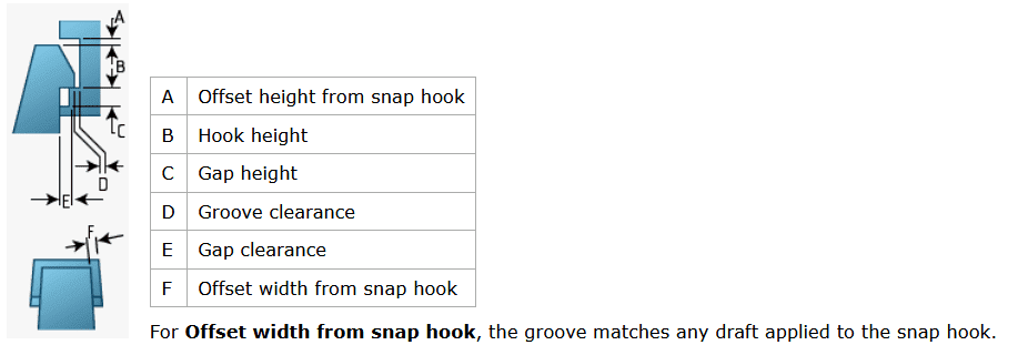
Now let us look at the lower portion of the Property Manager. This section is labeled Snap Hook Data. I have included labels for each of the feature dimensions below. For those of you familiar with Snap Hook design you will notice that there is not an option for controlling the angle of inclination. While this is an important dimension that affects mating friction and mating force, we will see that we can still create a perfectly usable snap hook without it.
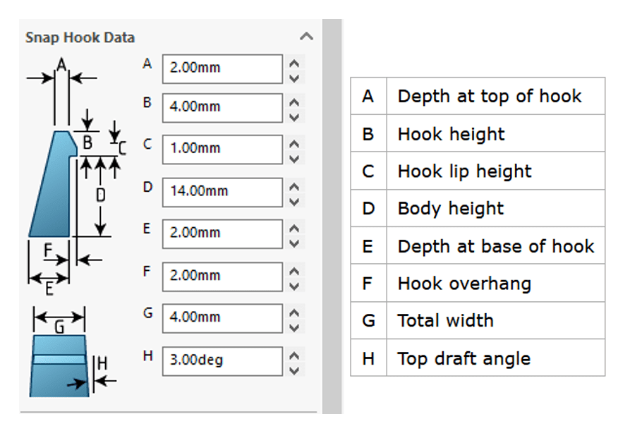
You can see my inputs above. These will vary depending upon your design and goals. For my example, I wanted to start simple and 3D Print some test parts. Then iterate if needed.
Once we have the Snap Hook feature created, we can then create the Snap Hook Groove. This is the groove that the snap hook will fit into. Start by unhiding the body for the top of the enclosure.
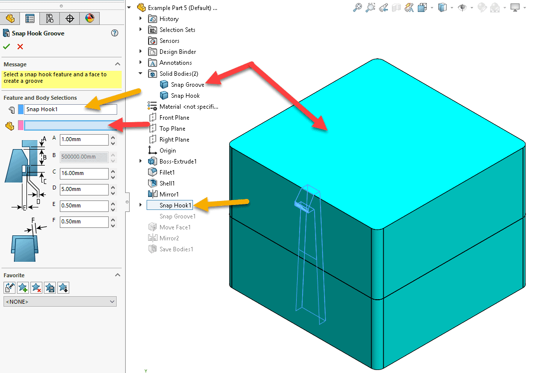
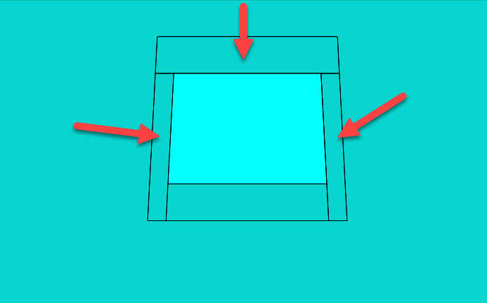
Now activate the Snap Hook Groove command. In the Snap Hook Groove PropertyManager, you need to select the Snap Hook feature (Orange Arrows) that you just created and then the Body (Red Arrows) that the groove will be applied. See image below.
We then have some dimensions that we can modify for the Snap Hook Groove (Shown below). I recommend changing the F dimension so that there is some clearance around the Snap Hook. I used 0.50mm (≈0.020in) of clearance in this example. The F dimension will automatically adjust the offset based on the draft of the Snap Hook.
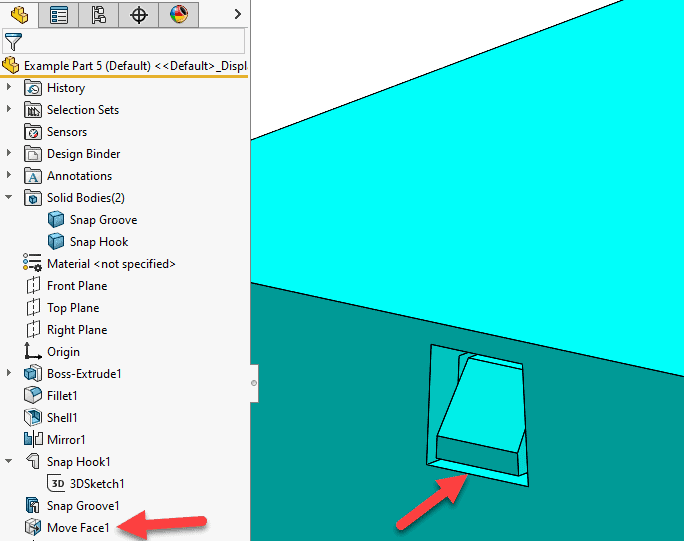
The image below shows the clearance around the Snap Hook.
A little tip here. I also recommend adding clearance under the lip of the Snap Hook. I applied a Move Face command.
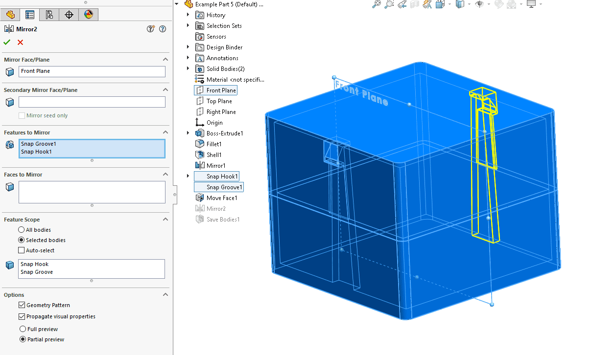
I then used a Mirror command to mirror the Snap Groove and Snap Hook Features.
Our enclosure is now complete!

If you plan on 3D Printing each of the pieces you can use the Save Bodies command to save the two bodies out as individual parts.
Check out Cameron Bennethum’s blog SOLIDWORKS Simulation – Snap-Fit Design and Optimization
Till next time everyone!
James Reeher
Application Engineer
Computer Aided Technology