Insight Basic Part Setup
A while back we started a blog journey through running Insight, a very powerful software package, included in the Stratasys Fortus line of Additive Manufacturing (3D Printers) equipment.
See a few of these posts with the links below.
- Tips for exporting your 3D CAD files into the STL file Format – STL Output settings for CAD
- Considerations for part orientations once you have a file to print – 3D Printing Orientations Guide Volume 1, 2, & 3
- A quick overview of the Insight Interface and general Settings – Insight Overview
- An overview of the latest enhancements to Insight – Insight 10.8 Enhancements (for new futures).
This post will deal with the basic settings and options to build your part.
To get started with your print Click File – Open and select your STL file. Pick an orientation based on using the face selection button

Or the automatic orientation option in the STL – Automatic Orientation menu. Pay attention to the “Method” Drop down box. I generally select “Surface Finish” When using the automatic option. This is very handy when working with parts without a flat face.
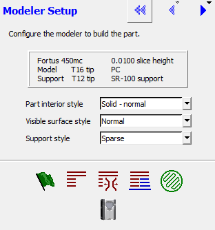
Referencing this image select the desired options from the drop down lists.
Part Interior style – We have the option (depending on machine and material) to run our parts in Solid, Sparse (sometimes referred to as Sparse LD), Spare HD, and Sparse DD. The difference between these is mostly to do with the Width of the bead of plastic printed compared to the width of the air gap between. Think of this like infill percentage if you are used to some of the home printers.
Visible surface style – Here we have the options for “Normal” end “Enhanced”. The difference here is the “Enhanced” Option will lay a very thin bead of plastic down with a slight overlap. The “enhanced” option should improve esthetics on the top layer of your builds.
Support Style – There are several different support options available. Usually I use the “sparse” option or the “smart” option. The “smart” option stands for “Save Material And Reduce Time”. Within these options the structure and toolpaths are changed and could probably take up an entire blog post to themselves.
Once these few options are selected there are two options to complete the build file for printing. The “Easy” button is the green flag, or Do-All. The Do-All button slices the model, generates support structures, then figures out the toolpaths one layer at a time. I rarely use this option anymore and prefer manually stepping through the process. Manually slicing the file, generating support, and toolpaths allows me to inspect each step along the way before moving to the next. For instance, If I found an issue in the slices, I wouldn’t need to waste time generating supports and toolpaths just yet.
Once your build is setup and toolpaths are created, you can send off to the printer! Keep a look out in the future for more Insight posts. Let me know in the comments if you have questions or have something specific you’d like to see about Insight.