Minimizing Support Removal Time with DfAM for FDM
Minimizing Support Removal Time with DfAM for FDM
Soluble support material is a feature unique to Additive Manufacturing and is responsible for enabling the seamless printing of organic geometries and build parts. In contrast to the many possibilities that soluble support material opens up, it also has downsides, particularly in Fused Deposition Modeling (FDM) printing. In FDM printing, soluble support material is notorious for increasing build times, the material cost of the part, and the amount of time dedicated to support removal during the post-processing step.
When it comes time to design a part via Additive Manufacturing, it is wisest to take the entire process into consideration. All too often, additive is viewed with a very siloed approach; segregating designing, building, and post-printing as three completely independent steps. Possibly because it is not quite as exciting as the first two processes, post-printing often gets left behind as an afterthought.
For optimal additive efficiencies, it is best to instead view the three workflow steps as integrated and cohesive. Read on to take a deep dive into FDM soluble support removal, and to learn about how your part orientation, support settings in the slicing software, and part design may impact support material usage and removal. These suggestions, along with the PostProcess Technologies’ DECI or BASE Support Removal systems for FDM, can drastically lower your FDM part cycle time.
Part Orientation
Orientation can play a huge role not just in the strength of your part, but in the amount of support material used during the print step (depending on part geometry).
Here’s an example of how orientation can affect the amount of support material required:
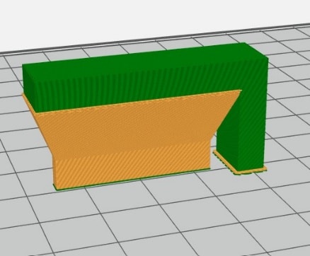
Figure 1
Figure 1 shows a L-bracket printed on its end, and Figure 2 shows the same L-bracket printed flat on its side. In the GrabCAD Print software screenshots, the green represents the model material of the part, and orange represents the support material required to print the part in that specific orientation. You can see that build time is minimized by ~58%, while support material usage is reduced by ~91% just by altering the build orientation. Long story short, this equates to a shorter overall part cycle time, as well as a lower part cost for you.
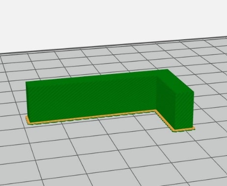
Figure 2
You can use slicing software like Stratasys’s GrabCAD Print or Insight (if you have a Stratasys FDM printer) to preview the build, and estimate the amount of time and material required. If you are an Insight user, there is an Automatic Orientation function that offers to “Minimize supports.” By choosing this, you will see various orientation alternatives, so you can choose the option with minimal support material. Remember, Insight is not always 100% accurate, but it can at least help you figure out if you are on the right track. This type of software is especially ideal for trying to minimize support material usage on complicated parts.
Slicing Software Support Settings
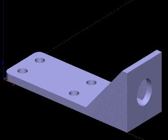
Figure 3
If your part design does not allow for alterations or changes, there are still methods to reduce the amount of support material required. For example, if you have a part as shown in Figure 3 in Insight, you can customize the amount of support material used by changing the “Grow Support” setting. The software is set at “Small only” by default, but in some cases, it can be modified to “No.” Check out Figures 4 and 5 for the before/after results (here, the red is model material and the gray is support material).
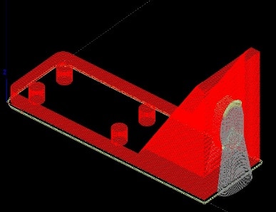
Figure 4
Altering this setting eliminates the support material that grows from the bottom of the feature (in this case a hole) to the build platform. This adds up to about a 10-minute reduction in build time (6% overall reduction) and 0.141 inᶟ reduction in support material (15% overall reduction) on this individual part.
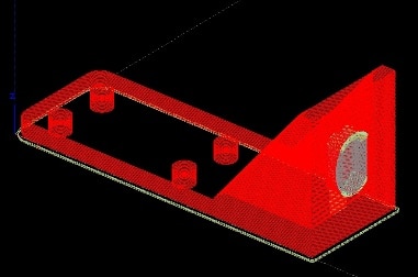
Figure 5
Part Design
Reducing support removal time can be as simple as strategizing your part design. How can you do this? Capitalize on the benefits of whatever print technology you are using. In FDM printing, users can take advantage of self-supporting angles and, in combination with part orientation, effectively reduce the amount of support material needed. Sometimes this can even strengthen your part design.

Figure 6
Let’s get into the basics of self-supporting angles. A self-supporting angle is the angle from a line parallel with the build platform, to the feature being supported (see Figure 6).
Typically, this angle is 45⁰, but any overhanging geometry that has an angle of less than 45⁰ will require support material. Specifically, the actual value is in the support settings in GrabCAD print, or, if you are using a Stratasys printer, in Insight. The actual value may vary based on the printed model material and the slice height that the printer is set at. For example, on a Stratasys Fortus 450mc, loaded with ASA material and printing at a slice height of 0.010”, the part will have a self-supporting angle of 43⁰, whereas Nylon 12CF is 50⁰. So, this angle could change when switching materials and/or slice heights.
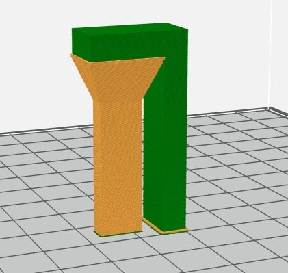
Figure 7
While designing an FDM part, it’s critical to understand the orientation that the part will be printed in, and how you might be able to utilize efficiency tricks like self-support angles in your part design. Remember, this will help reduce the support material needed, and speed up the support removal process. Below is an example that illustrates how effective self-supporting angles can be in saving on build time, support material usage, and the time spent on removing support material.
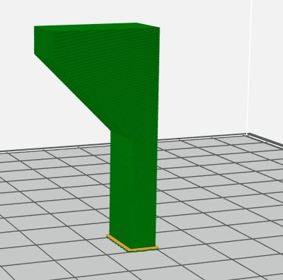
Figure 8
Remember, it takes time, patience, and practice to design parts that take full advantage of Additive Manufacturing. As you begin looking at the lifecycle of designing, building, and post-printing in AM, don’t hesitate to explore the automated product offerings of PostProcess Technologies, specifically the DECI and BASE systems, for FDM. Both of these systems are developed with patented Volume Velocity Dispersion (VVD) technology, which serves to efficiently remove support material and streamline overall workflows.
Authored by PostProcess Technologies