Stratasys 3D Printers: Print Head Alignment for PolyJet Desktop Printers
Print Head Alignment for PolyJet Desktop Printers
You may find your parts have some rough edges over time or after replacing or swapping your print head locations on your Objet printer. This can be due to the heads being out of alignment and need to be adjusted. Doing the adjustment is fairly automated and easy to do. You will need your clear transparency sheets, scotch tape (optional), and a magnifier or loupe to look at the print to do this.
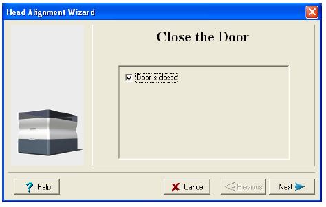
With your Stratasys Embedded Printer Software open on the desktop and the printer lid closed, go to Options > Wizards > Head Alignment to start the procedure. Click the “Next” button to activate the wizard and tell the machine the lid is closed which will home all of the axis.
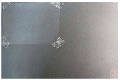
You will need to cut your transparencies in half, width wise, and place them on the left edge of tray. You can use scotch tape on the right side to hold the piece down to the tray. Alternatively, you could use a few drops of alcohol from your spray bottle to create suction between the sheet and tray.
Depending on how warm the machine is and how the UV lamp fires, it will take up to 20 minutes to print this out.
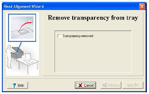
Once the print is completed open the lid, remove the transparency, and click the “Next” button from the tray and get the magnifier to be able to see the print.
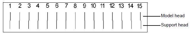
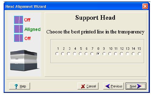
You may need to hold the transparency up to a light to see it better. What we are looking at is 15 lines which will display an offset to the left or right. The top line is the model head and lower is the support head. The model is stationary so we are looking at the lower line to see where it is most centered with the top line. Number 8 is perfect and where it should be, but if not just choose the most centered one and indicate that by picking that in the software. The software will self-calibrate to try to get the most centered line to the 8 position.
(Representation of the print)
In the software you select the mot centered line and proceed to the next step.
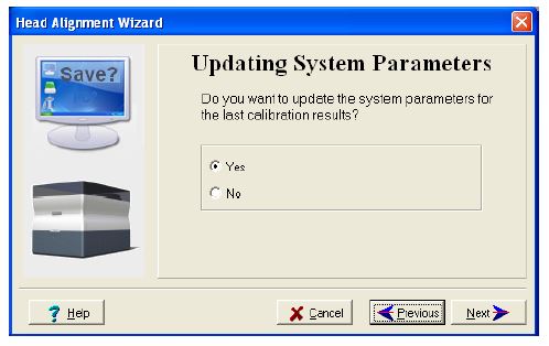
This will then allow you to update the system parameters.
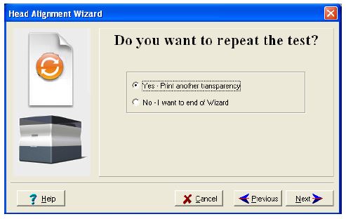
You can then either reprint the transparency to check that it is now in fact centered or proceed to close the wizard. We recommend to recheck the results if it is off more than +/- 2 of the number 8 line.
After this is done, we recommend that you print the serviceengineerfile.stl to check for accuracy.
Dominick Damato
Field Service Technician
Computer Aided Technology