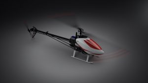
Rotation Animations using SOLIDWORKS Visualize Professional
Earlier this month we showed how to download and install SOLIDWORKS Visualize. Today I wanted to talk about some of the features found in SOLIDWORKS Visualize Professional; specifically, how to add motion to parts cameras, and lights.
SETUP
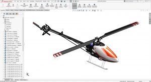
First we’ll start with the model in SOLIDWORKS; I will need to set up the assembly structure and basic materials. This model was created by one of our Application Engineers, Kris Dubuque, from our Beaverton Oregon Office.
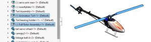
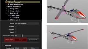
Since the goal here is to show the main rotor and tail rotor in motion, I will group the components into two sub-assemblies. You can control this structure in SOLIDWORKS Visualize, however this will help save us some time since this is easy to do in SOLIDWORKS.
The next step is to assign different appearances to all the parts. This can be adjusted in SOLIDWORKS Visualize but it is easiest to assign a common appearance to all like material parts in SOLIDWORKS first. Visualize will recognize appearances applied to faces, bodies, and components. Notice the Canopy and main rotor blades have multiple appearances applied. This is done using the ‘Split-line’ command which splits a face (or faces) into multiple faces. Appearances are then applied to each face.
IMPORT
To import my model, I start by creating a new visualize project then either drag-and-drop the SOLIDWORKS assembly into the window, or press CTRL+I. Once I have selected the model to import into Visualize, I will use the part grouping option ‘Retain Structure’. This option will honor the sub-assembly structure and appearances I have already applied in SOLIDWORKS.
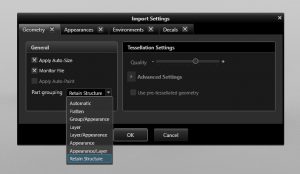
You can also choose to ‘Monitor File’. Using this option will allow any assembly or component edits to be updated in visualize. Keep in mind that some edits may cause unwanted results in visualize due to regrouping of components, or assigning additional appearances to the model. Major edits to the model will most likely require you to recreate the project in SOLIDWORKS Visualize.
Upon importing the model, we can see that the appearances have all been imported but more importantly, the structure of the original assembly is intact.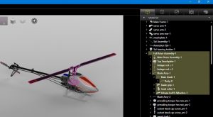
TIP: if you cannot see the model tree or other tabs in the interface, press ‘SPACEBAR’ to toggle between Easy and Regular interface modes.
ADDING MOTION
Next I will need to set the blades in motion. To do this, I right-click on the component I need to rotate and choose ‘Add Rotation Animation’.
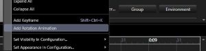
You will notice a red dot is now added to the name in the tree. This indicates the part is in motion.

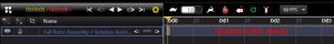
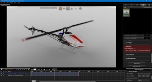
Now would be a good time to show the timeline by going to ‘View -> Show Timeline’ or by pressing CTRL+L. The time line has a new line added for the rotation that defaults to 5 seconds in length and 360 deg rotation around the Y axis. Double-Click the animation duration area to open ‘Animation Properties’ to the right of the timeline.
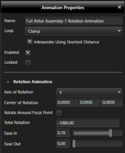
Animation properties will allow us to make edits to the total number of degrees in the rotation, reverse the rotation (use negative integers!) and change its pivot axis. You can also adjust ease in/out if you would like to show the part accelerating/decelerating to/from the total rotation value. There are also options to adjust the center of rotation.
Instead, I will adjust the ‘pivot’ position. Since this part is symmetrical around the pivot axis I want to use, I simply pick the group from the model tree, and from within the group properties window press the ‘Group’ button next to ‘Pivot Center…’ This will align the pivot axis to the center (volume center) of the group.
I then repeat this process with the tail rotor, but instead use the X axis and also reset the pivot location to the center of the component group. Also, this helicopter has a direct drive to the tail rotor with a 4:1 ratio. I used -1440 deg to accomplish this.
TIP: This method of adding and adjusting rotations can also be done with cameras and lights. Right-click the camera or light and choose “Add Focus Rotation Animation”.
MOTION BLUR
Finally, I would like to add some motion blur for still photos. Go to the ‘Cameras’ tab and select the default camera in the project. Scroll to the bottom of the properties window and enable motion blur. You can adjust the shutter speed in milliseconds.
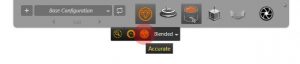
For my final render I compressed the animation time to a fraction of a second for both rotors since the main rotor speed for this helicopter is between 2800 and 3500 RPM. Once I have the RPM dialed in, I can more accurately play with the Shutter speed until I find a setting to my liking. Note that in order to see the effect of the motion blur, you will need to use ‘Accurate’ render mode.
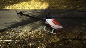
Adding motion and blur with SOLIDWORKS Visualize Professional can add that additional “pop” to still images where you want to convey circular motion quickly and easily.
If you or anyone on your team would like to know more about how to use SOLIDWORKS Visualize or would like to suggest a topic for the future, please email us at support@cati.com
Alex Worsfold
Application Engineer
Computer Aided Technology, Inc.