Simulation Walkthrough: Trebuchet cross beam analysis
Introduction:
So, you’re designing a trebuchet and you need to know if the main loading cross beam is strong enough. Where would you begin? What type of study should you use? These questions and others will be answered in this blog. The main objective is to start from an unaltered CAD file and describe the process to set up an appropriate analysis.
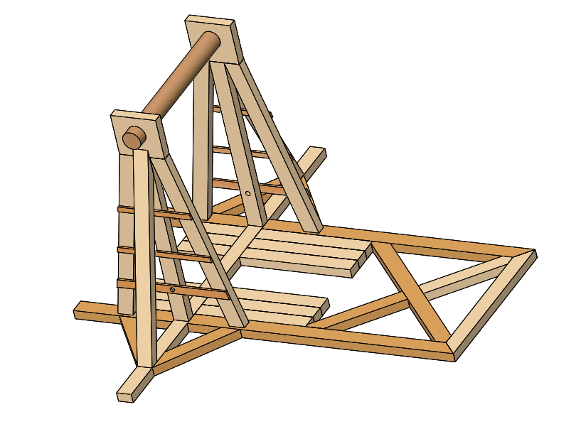
Now, I do realize that this design is incomplete. Let’s start an analysis anyway. The ability to create an analysis during the design phase is one of the best arguments to have Simulation embedded into your SOLIDWORKS CAD package.
Problem Setup:
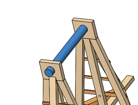
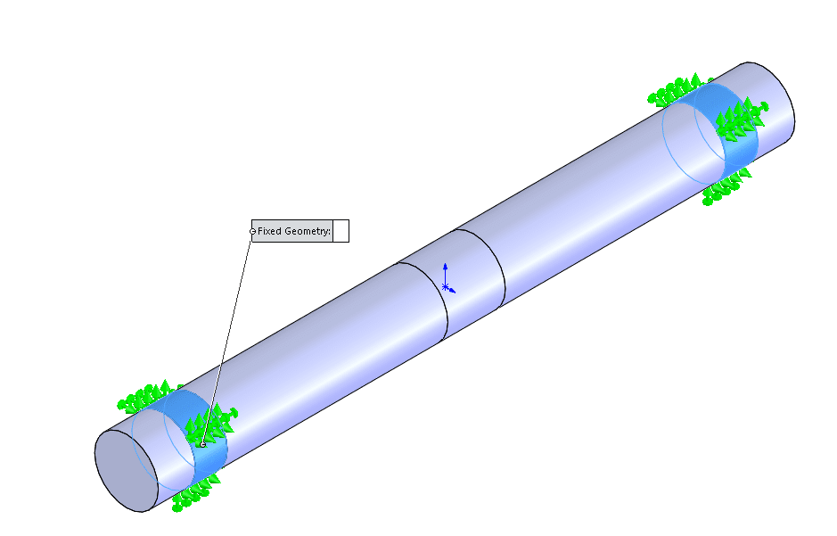
We have identified the beam, highlighted in blue above, as a critical design component. This beam must hold up to the load of the counterweight, bucket, and projectile. We are going to run an analysis on the beam itself to reduce the size of the problem and computation time. The beam attaches to the supports on the side and the beam holding the projectile in the middle. I will need to assign these loading conditions accurately so the results will also be accurate. This beam has 3 faces; 2 end flat faces and 1 long cylindrical face. I’ll need to break these up into multiple faces in order to apply the loading conditions. The first thing I do is create a sketch, shown below.
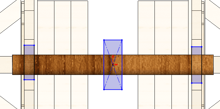
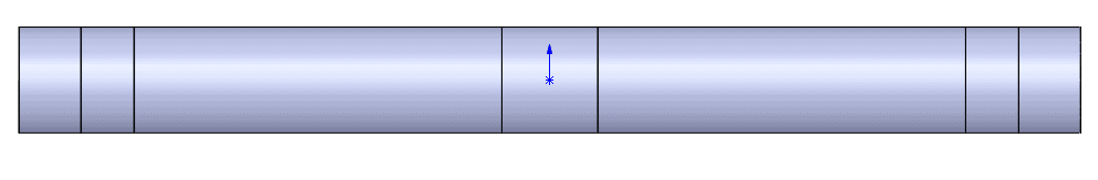
Then I’ll need to use the Split Line command to break this single cylindrical face up into a total of 7 faces. But the only areas I’m concerned about are the areas inside the rectangles I sketched.
For more information on Split Lines, please visit the SOLIDWORKS online help. Here’s a link for your convenience: http://help.solidworks.com/2019/english/solidworks/sldworks/hidd_dve_pline.htm
Study Selection:
Next, we need to select the type of simulation study. SOLIDWORKS Simulation has many different types of studies but the main types we would consider for this problem are Static, Dynamic, Nonlinear, and Fatigue. Which of these four should we use? The Nonlinear study would be great if we think this beam will be stressed above yield and if the load cannot be modeled as linear with respect to time. For this application, we can simply apply the worst-case load and any variation in load with respect to time is irrelevant. The Dynamic study is great for base excitation (the type of load that an Earthquake would generate) so that does not apply in this case. Fatigue only becomes relevant when a load is cycled hundreds of thousands of times which it won’t for this trebuchet. And so, we have determined that the Static study is the most appropriate for this application.
Defining Fixtures:
Once the study type is selected then material, fixtures, loads, and mesh must be defined. The order of operation does not matter for this part. I will start with fixing the motion of this beam by fixing the cylindrical faces near the end of this beam (see below).
Defining Loads:
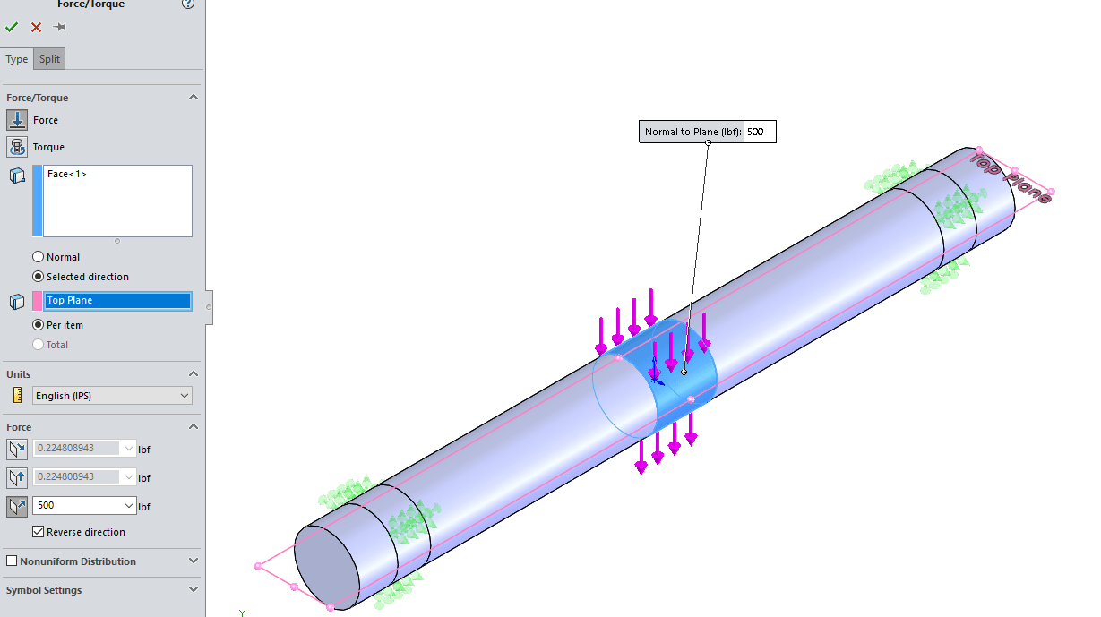
Then apply a load. We must be careful to assign the load in the correct direction, so we chose the Top Plane as the reference. Then apply a load of 500 pounds normal to the top plane and check to ensure the arrows point down.
Defining Material:
We must assign the material to this beam. We select wood but we must know something about wood in general. The amount of weight that a beam made of wood can hold depends on the orientation of the wood beam. This is due to the grains that develop while a tree grows. This type of material is classified as orthotropic and requires material properties specified in the x, y, and z direction. Learn more about orthotropic materials and how to define them.
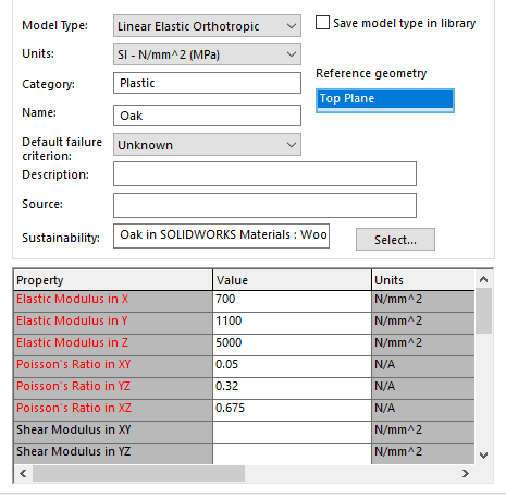
I selected the Top Plane as a reference and Linear Elastic Orthotropic as the material type. Then it’s just a matter of inputting the Elastic Modulus and Poisson’s Ratio in x, y, and z directions.
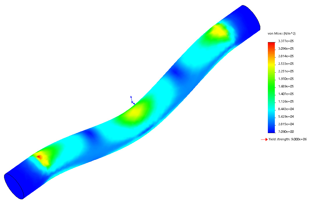
Once a material is assigned, use curvature-based mesh with default values and run the simulation!
In this blog, we described the process of how one might go about developing a SIMULATION study. If you would like assistance on how to do each step, please consider taking our Simulation Standard instructor-led 3-day course.
Matthew Fetke
Application Engineer, Simulation
Computer Aided Technology, LLC