SOLIDWORKS: Exploring The Width Mate
SOLIDWORKS has over twenty distinct types of mates that we can use to constrain our components in an assembly. These various mates are divided into three main categories: Standard, Mechanical, and Advanced. For this post, lets dig into the Width mate, found in the Advanced group of mates.
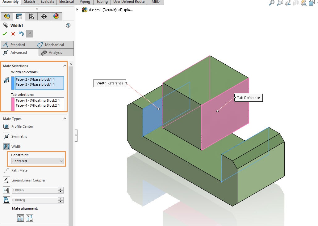
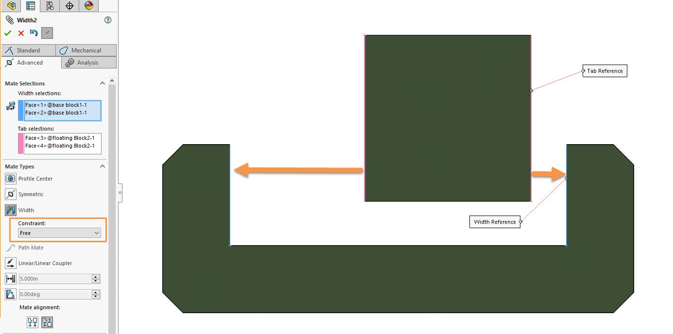
The general idea of the Width mate, is that it centers one part(referred to as a Tab) between two planar faces. For my examples, these two planar faces are on a 2nd part. This is not a requirement for a Width mate, and we could even use reference planes. The Width mate interface can be a bit confusing with its two main selection boxes. The Width selection is for the “outer” faces/planes, while the Tab faces are the ones of the part that will be centered between the Width faces. There are also options for defining “Constraint,” that we will examine.
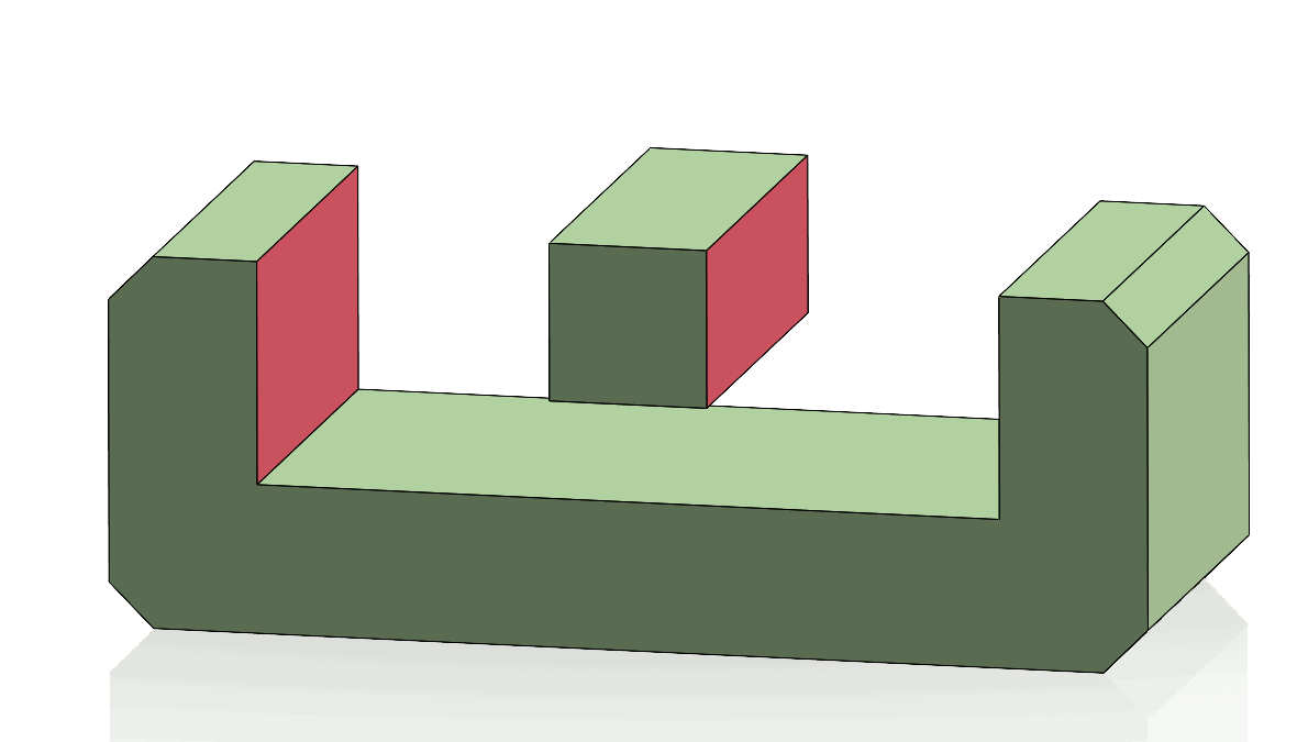
The Width mate is wonderful for capturing your design intent for locating components. If the inner block is modified, and reduced in size, the width mate will update. In this case it forces the smaller block to remain centered.
Here are a few more examples of the Width mate selections, and the end result. In addition to our previous example, it also works great with cylindrical geometry and even nonparallel faces. 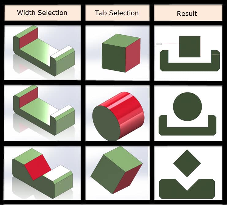
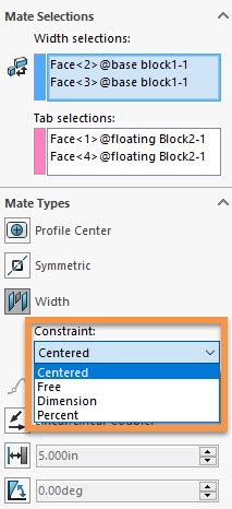
Let us take a closer look at the “Constraint” options for the Width Mate. You will see we have four choices: Centered, Free, Dimension, and Percent. The Centered option will constrain the Tab selections to the middle of the Width selections. This is what the Width Mate selects by default, and is shown in our previous examples. Let’s take a look at these more interesting options where we can select “Free”, “Dimension”, and “Percent”.
Out of these options, “Free” is the most powerful. It provides a dynamic control of the “Tab” and permits it to move back and forth, as long as the Tab faces remain inside the “Width” faces. This realistic degree of freedom will function like a “Limit Mate” where the Tab has a range of motion.
The “Dimension” constraint will lock the Tab part from moving side to side. It is constraining it with a dimension from the outside face of the Tab selection to the inside face of the Width selection. This functions just like a standard Distance mate.
![]()
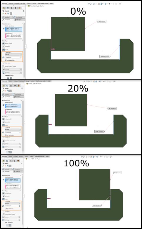
The Percent constraint uses a percentage to control the position of the Tab component. This percentage is based on the full range of motion the Tab has between the Width selections. Here you can see the same example with different values for the percentage parameter motion.
As you can see, the Width mate is an immensely powerful and flexible option for making sure your design intent is captured and the assembly performs the way you need it to. Hopefully this shines some light on the subtle constraint options and encourages you to take full advantage of the Width mate in SOLIDWORKS.
Greg Buter
Application Engineer Manager
Computer Aided Technology