SOLIDWORKS Flow Simulation – Which will fill first?
Now that SOLIDWORKS 2018 has been released for a few months, I’ve had the opportunity to look through many of the new features. My primary interests are the new features and functionality included in the Simulation suite of products. When our Technical Team was writing about many of the new features in 2018, more than a few piqued my interest. One specific enhancement for SOLIDWORKS Flow Simulation really piqued my interest to investigate further. I found an interesting model to try it out on – the “buckets” picture that I’ve seen floating around the internet for some time. You know you’ve seen the one. It asks you which bucket will fill first. If you’re an expert in fluid dynamics, you can easily figure out the correct answer. I’m going to use SOLIDWORKS Flow Simulation and the Free Surface analysis option to prove the answer.
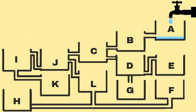
I started with building a multi-body part model using a sketch picture for reference. I sketched lines as close to the center of each of the bold lines from the reference photo. Then I created a thin extrude of all the lines to build the geometry of the ‘buckets’. From there, I capped the ends of the thin extrude and build an enclosure all around the perimeter. This creates the internal volume that I need for the SOLIDWORKS Flow Simulation project. I also created a few reference volumes in several of the ‘pipes’ and on top of several of the ‘buckets’. More on the need for these later.
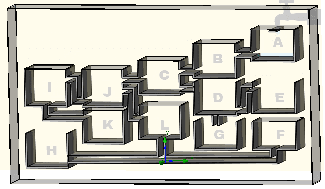
In setting up the SOLIDWORKS Flow Simulation project, I use the options for gravity, transient analysis, and Free Surface flow. To ensure there is a sufficient number of cells for each of the flow channels, I used a Local Initial Mesh on the thin-extrude bodies where water will flow from bucket to bucket by increasing the partial cell refinement level. I also included a local initial mesh on the reference volumes within the pipes to increase the fluid cell refinement level. The remaining reference volumes on top of the ‘buckets’ were used as an internal lid to track volume flow rate of water, should any spill out the top of a single bucket. I also created volume flow rate goals for the inlet, each of the internal bucket lids, and an equation goal to sum the ‘bucket lid outlet’ water flow rate. Finally, to speed up the analysis, I set the computational domain as a 2D Simplification problem using the XY Plane a reference. It may seem like a lot of setup, but the goals will allow me to determine which bucket will first – the answer to the question at hand!
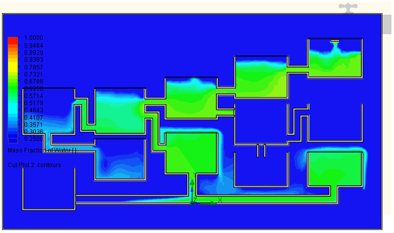
Let’s review the SOLIDWORKS Flow Simulation project results after solving this transient analysis for ten seconds. If I look at a cut plot for mass fraction of water, it appears that two of the buckets are filled to the top with water.
I could change the same cut plot and review pressure results, but that would only confirm what I already knew – the highest pressure will be in the lowest pipe. The answer can be found in the goal plots. At approximately 8 seconds into the analysis, the volume flow rate of water for bucket F is approximately 45% of the inlet volume flow rate of water. None of the other buckets at this time point have more than 2% of the inlet volume flow rate of water exiting through the lid.
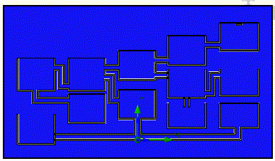
Another view of the buckets filling with water can be created by using the SOLIDWORKS Flow Simulation Transient Explorer.
The next time you see one of the ‘which will fill first’ pictures on the internet, you can do one of two things: ignore it or use SOLIDWORKS Flow Simulation to find the answer! Now go make your products better with SOLIDWORKS Simulation!
Bill Reuss
Product Specialist, Simulation
Computer Aided Technology