SOLIDWORKS Visualize: Rendering Glass and Liquid
Many new users to SOLIDWORKS Visualize might try rendering a glass, with some kind of clear liquid inside, and quickly realize that something is terribly wrong. There are several key things that will turn your renderings from confusing, to awesome, with a few simple changes.
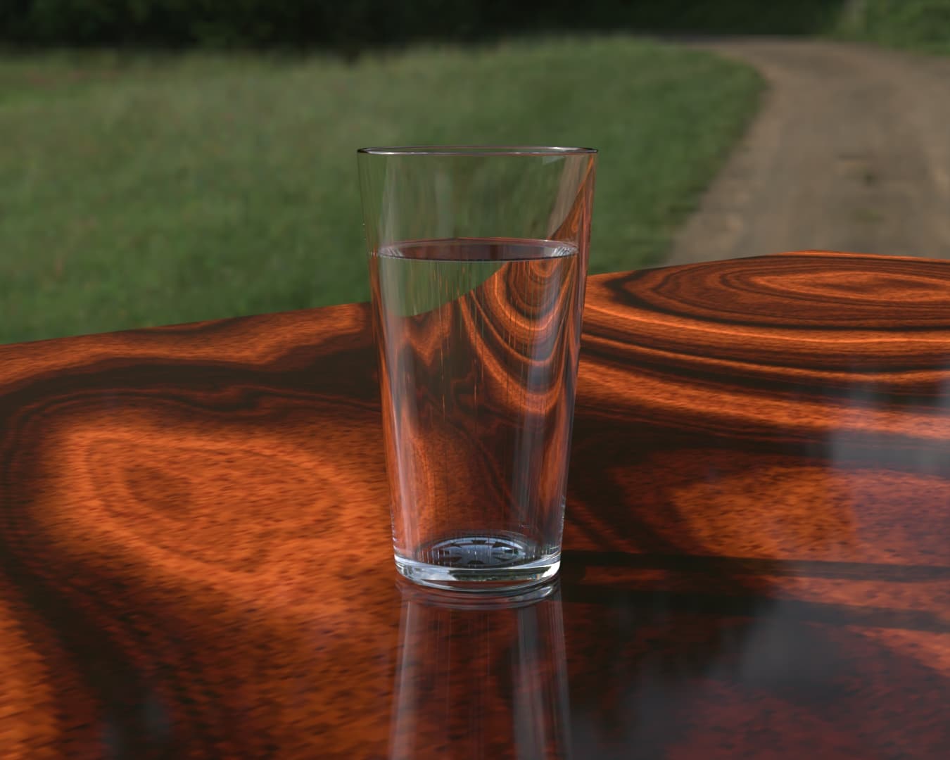
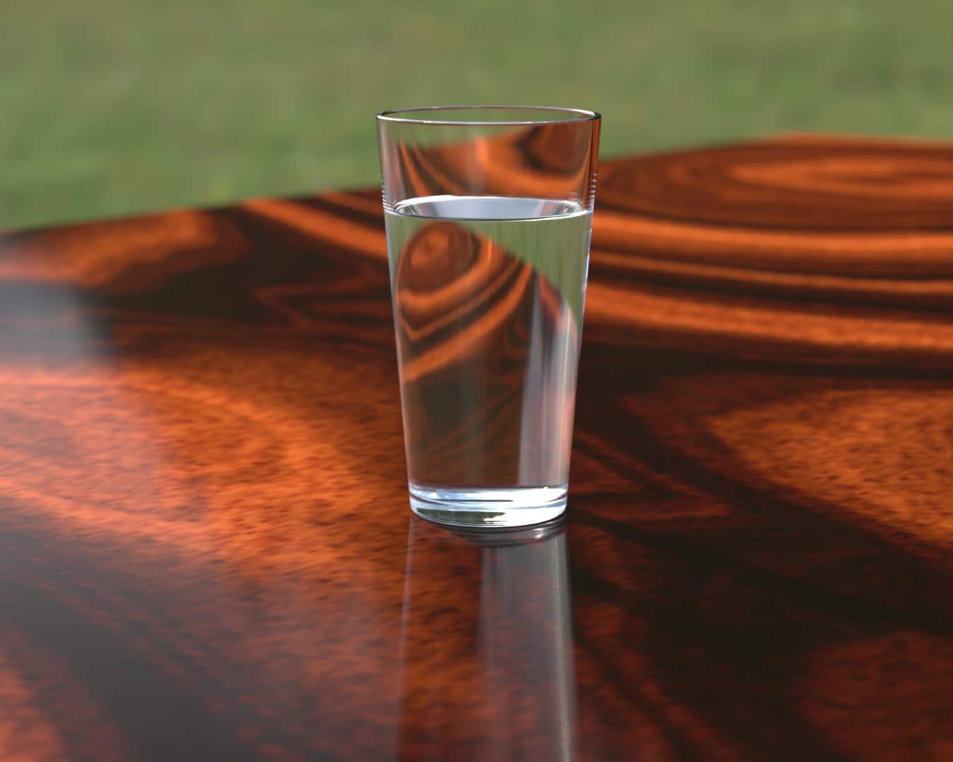
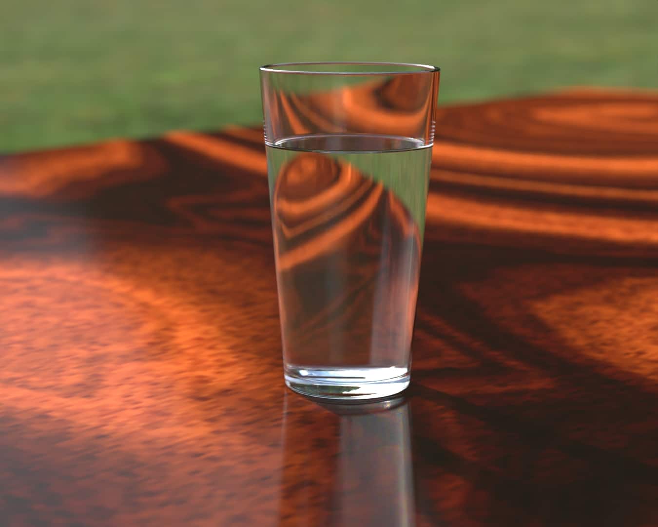
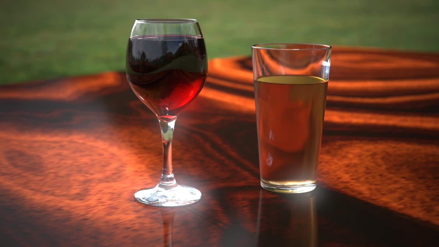
The above image has all the necessary components, a floor, and nice reflective environment, glass with correct refraction and light dispersion, and water with correct refraction and volumetric effects.
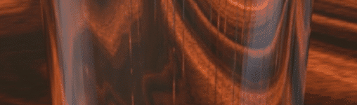
But what about these vertical lines?
And this crazy shape at the bottom?
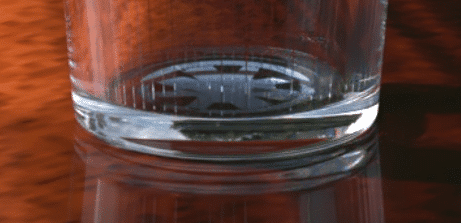
What causes these artifacts?
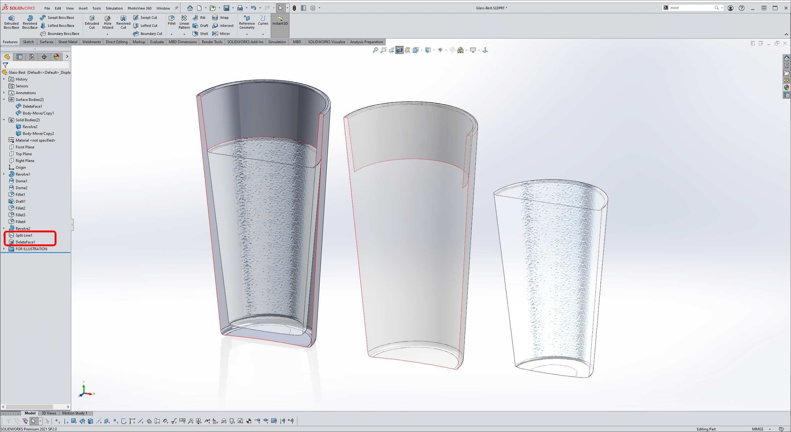
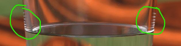
Tessellation! The model is built with an inside and outside surface for the glass, along with the water touching the boundary of the glass. The problem with modeling this way is a very small difference between the number of polygons needed to make the glass and the water. Intermittently around the two surfaces, the polygons intersect each other, and what we are seeing in the rendering is air or empty space between the glass and the water.
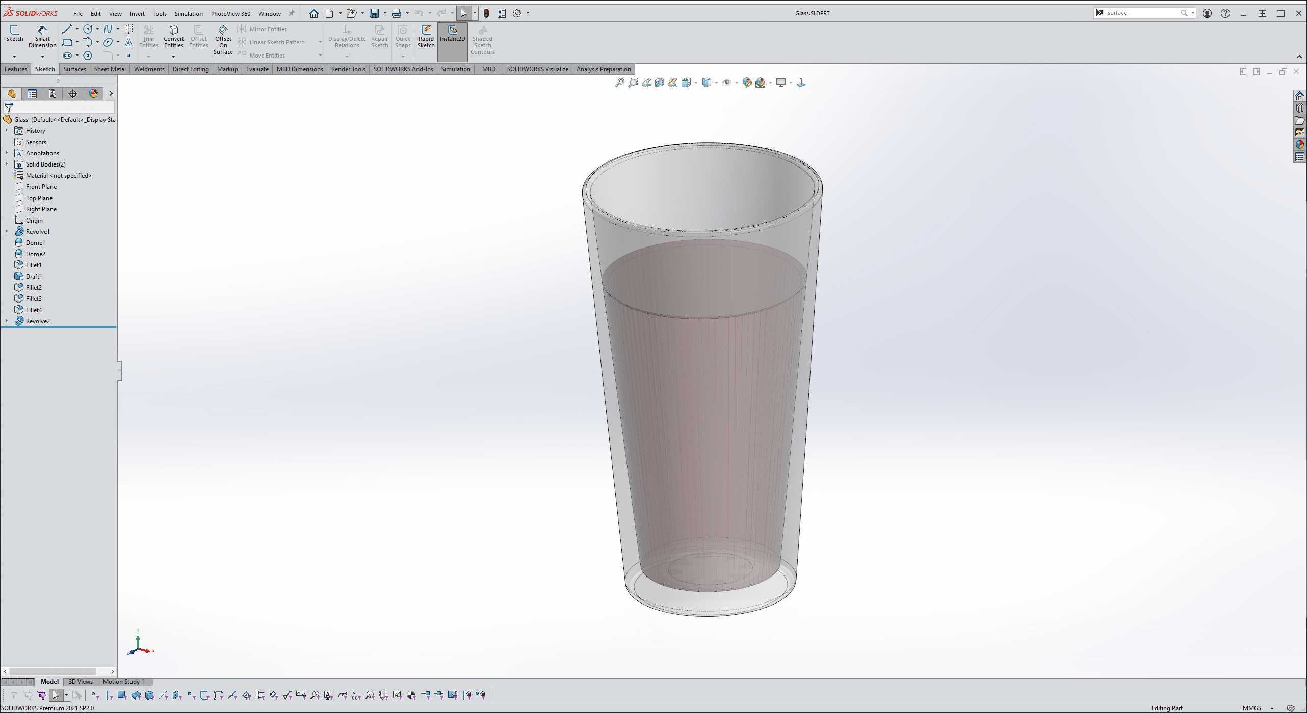
We also see this intersection problem in SOLIDWORKS before sending to Visualize.
So how can I fix this?
There are two solutions, and each will produce a slightly different effect.
Delete one of the inside faces.
This first method will require adding a couple more features in the tree. One to split the inside face of the glass at the top of the water, and delete face, to remove the glass-water interface surfaces.
This looks MUCH better, now I cannot see the interface between the water and the glass (just as in real life). But is it accurate? Let’s take a look at one more solution and then compare.
Increase the Intersection.
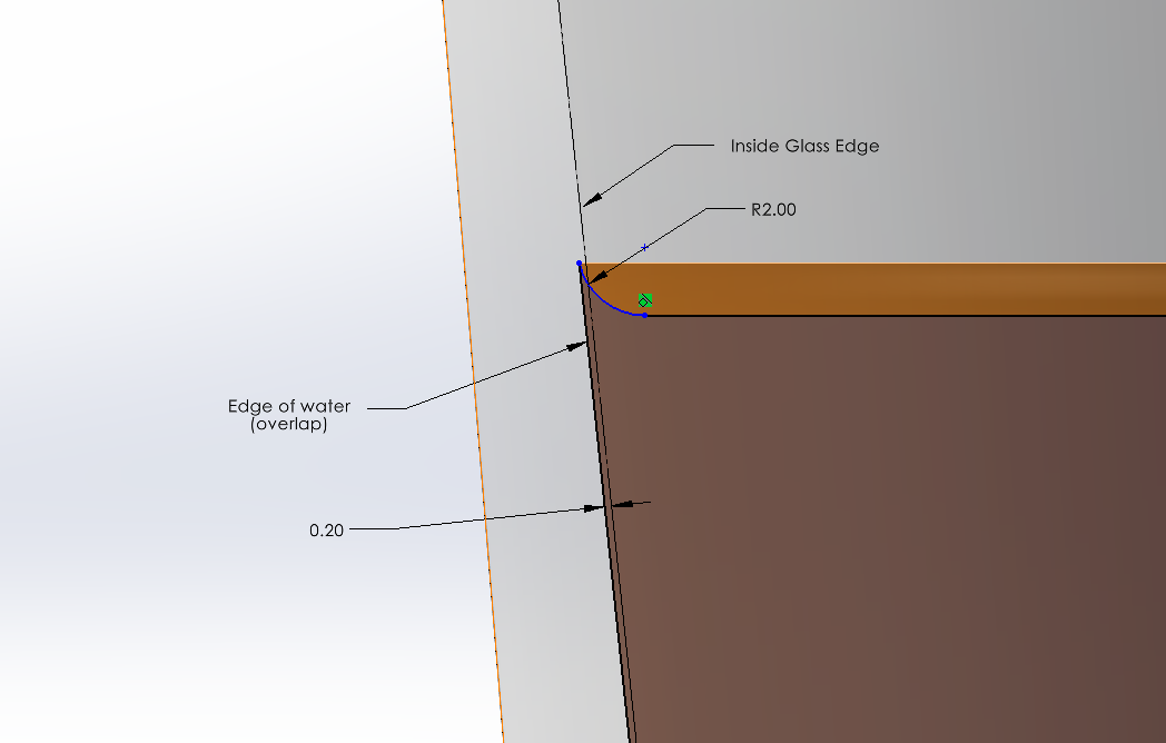
Wait, I just made an interference, isn’t this bad? Wouldn’t I want to go the other way and make a gap?
No, by increasing the size of the water, I’m cheating the interface between the water and glass which will eliminate any air gaps. However, you may find that you need more overlap depending on the size of your tessellated model.
Notice too, for extra effect, a small fillet around the edge of the water to simulate the water tension.
Did you know that you can control the level of tessellation before sending to Visualize? Use with CAUTION! Large models will produce MANY POLYGONS! However, this works great for those close-up models!
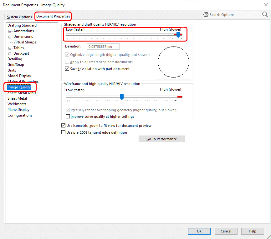
Turn the dial to 11, we’re going full tessellation!
Can you see any differences between the original, the delete face method, and this one?
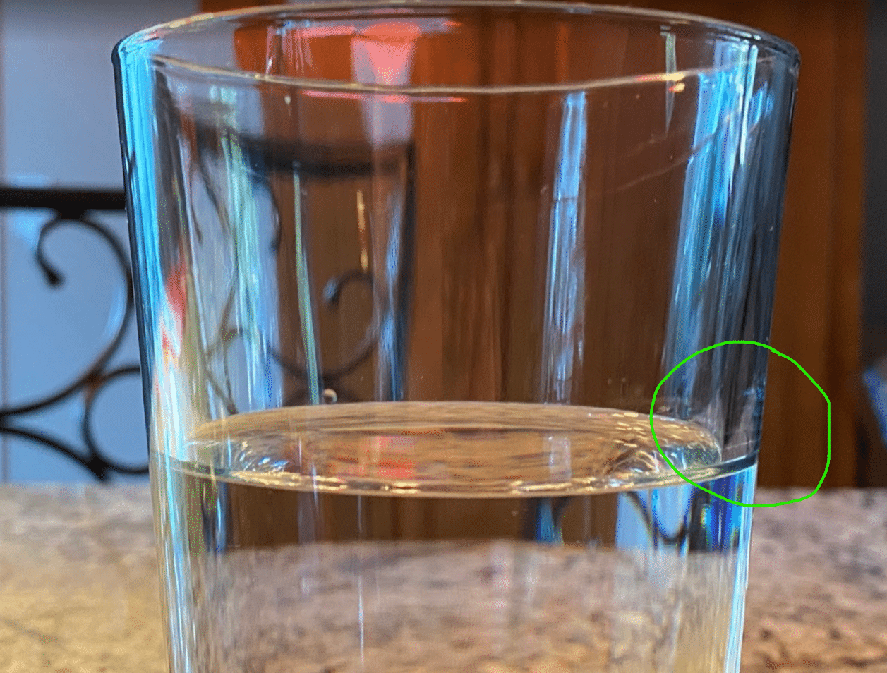
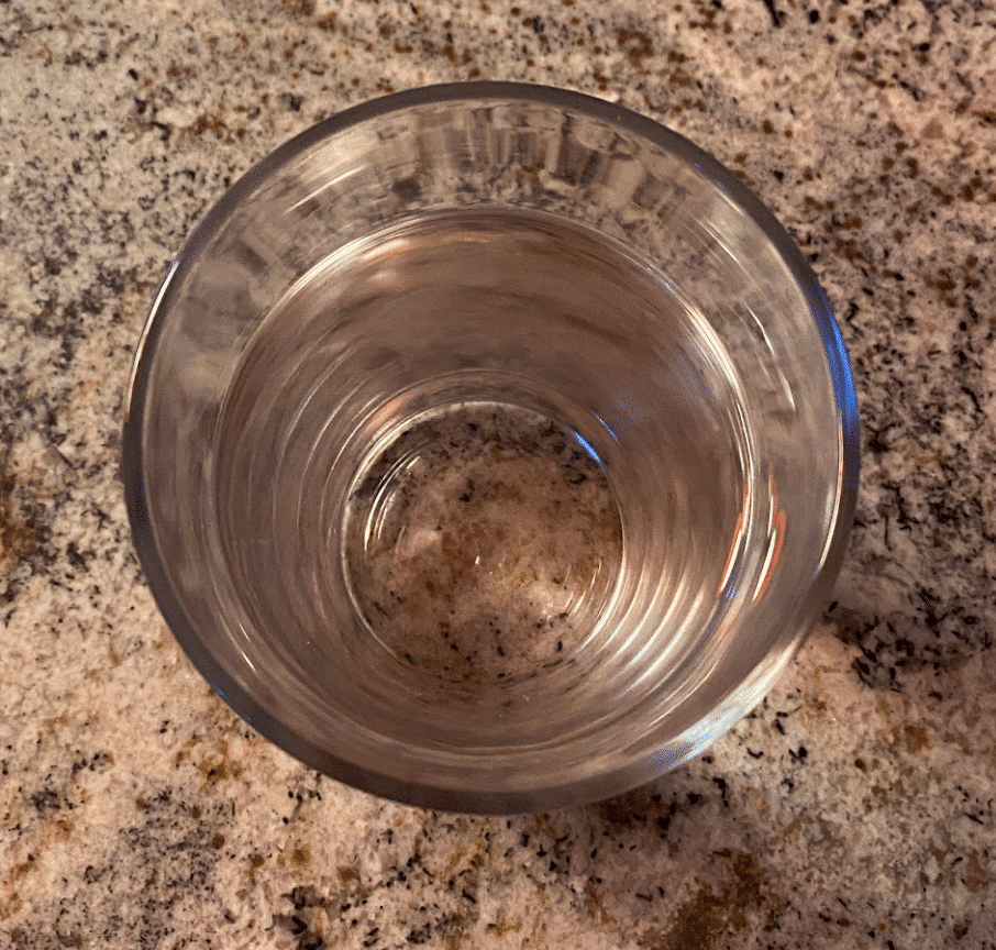
Wait, what are these lines?
These are simply just a reflection of the top water surface tension edge. You can observe this same effect on the real subject.
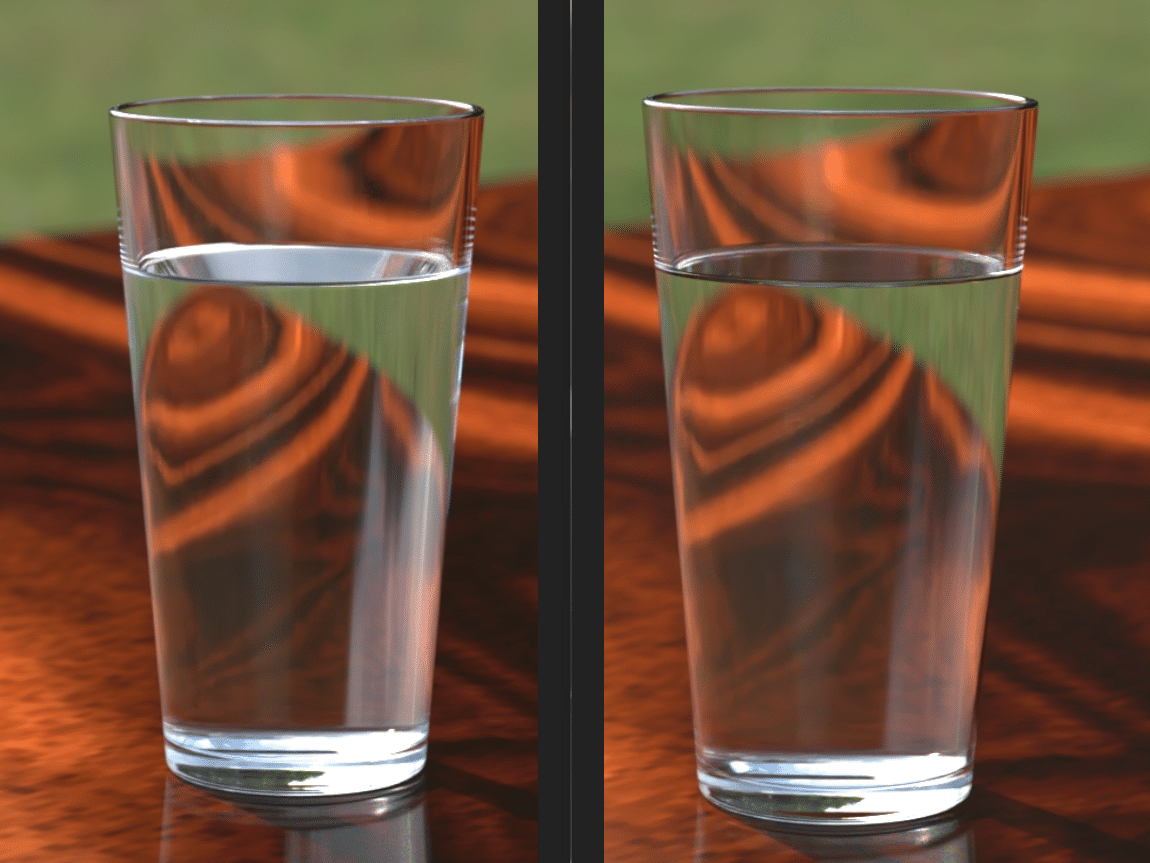
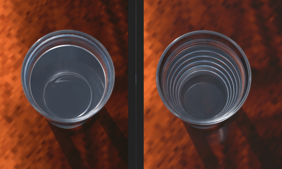
What’s going on with the top surface of the water? The left image is using the Delete Face Method, while the right image is the Intersection of water and glass. What is causing this effect?
Using delete face, there are not enough faces to account for all the correct reflections. So, what we are seeing in the left image, on the top surface, is the reflection from the OUTTER face of the glass. The image on the right produces the correct effect where the refraction and reflection has been correctly reproduced.
But how can we be sure? Let’s look from the top.
Again, delete face on the left, Intersection method on the right. From this view things look quite different. Which is correct?
The Intersection method is the clear winner here! When using the delete face method there simply are not enough faces to reproduce the correct reflections from the sides and top surface of the water.
There is one other aspect that is being correctly reproduced when using the intersection method, can you spot it? Send us an email!
For those that want to replicate my scene and materials, here are my settings:
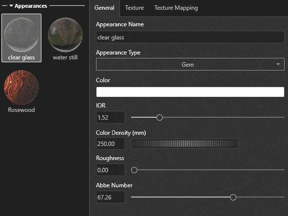
Gemstone type is important to correctly disperse the light and produce rainbow effects in the glass.
IOR or index of refraction is paramount to a correct looking render. Pane glass is 1.52.
For added affect, change the color, and set Density lower for more vibrant coloring.
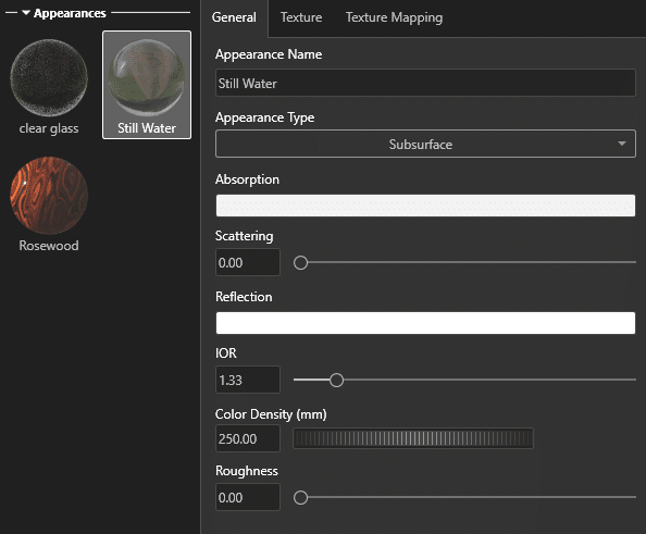
Subsurface correctly illuminates the depth of the water. This is especially helpful for simulating wine, beer, whiskey, etc.
Slightly increasing the scattering setting will produce a milky color for those unfiltered micro-brews.
Color and Density again go hand-in-hand here, for those Dark Stouts, or light Amber brews.
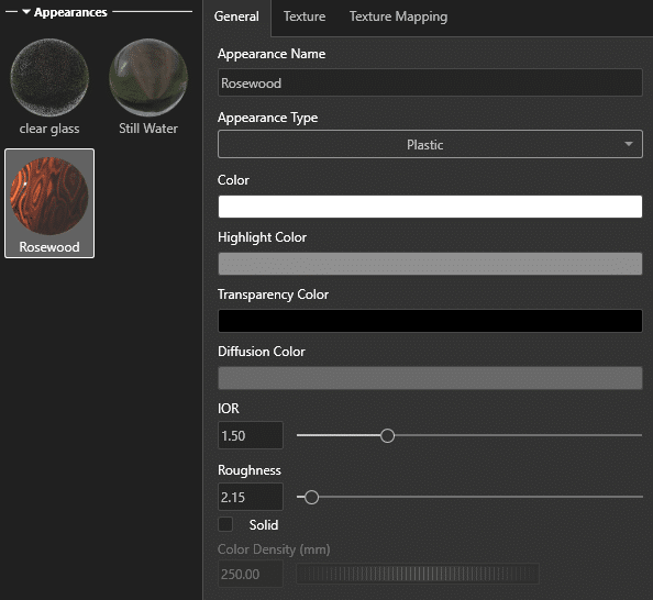
Who doesn’t love Rosewood?
Set Roughness and Diffusion color to liking.
Cheers!
Alex Worsfold
Application Engineer, Visualize Specialist
Computer Aided Technologies, Inc.