The Holster Project: Design to Manufacturing Series (Part 4)
 If you’ve been following along with our Design to Manufacturing Series, then you know that we’re on a mission to create a fully functional headset and cellphone stand. To do this, our Application Engineers are utilizing the entire suite of SOLIDWORKS 3D CAD software as well as additive manufacturing technologies including 3D printing and 3D scanning. For this particular entry, we’ll take a look at some of the tools that can help us identify, solve, and determine how we should proceed with our design process.
The Holster Project
Some of the AE crew are working on the Holster Project. The Side Holster design did come with a few challenges that need to be overcome. In the image below, you can see that the manner in which this design interacts with the laptop monitor will cause a number of reaction forces and moments that will most likely cause the Holster to fall off.
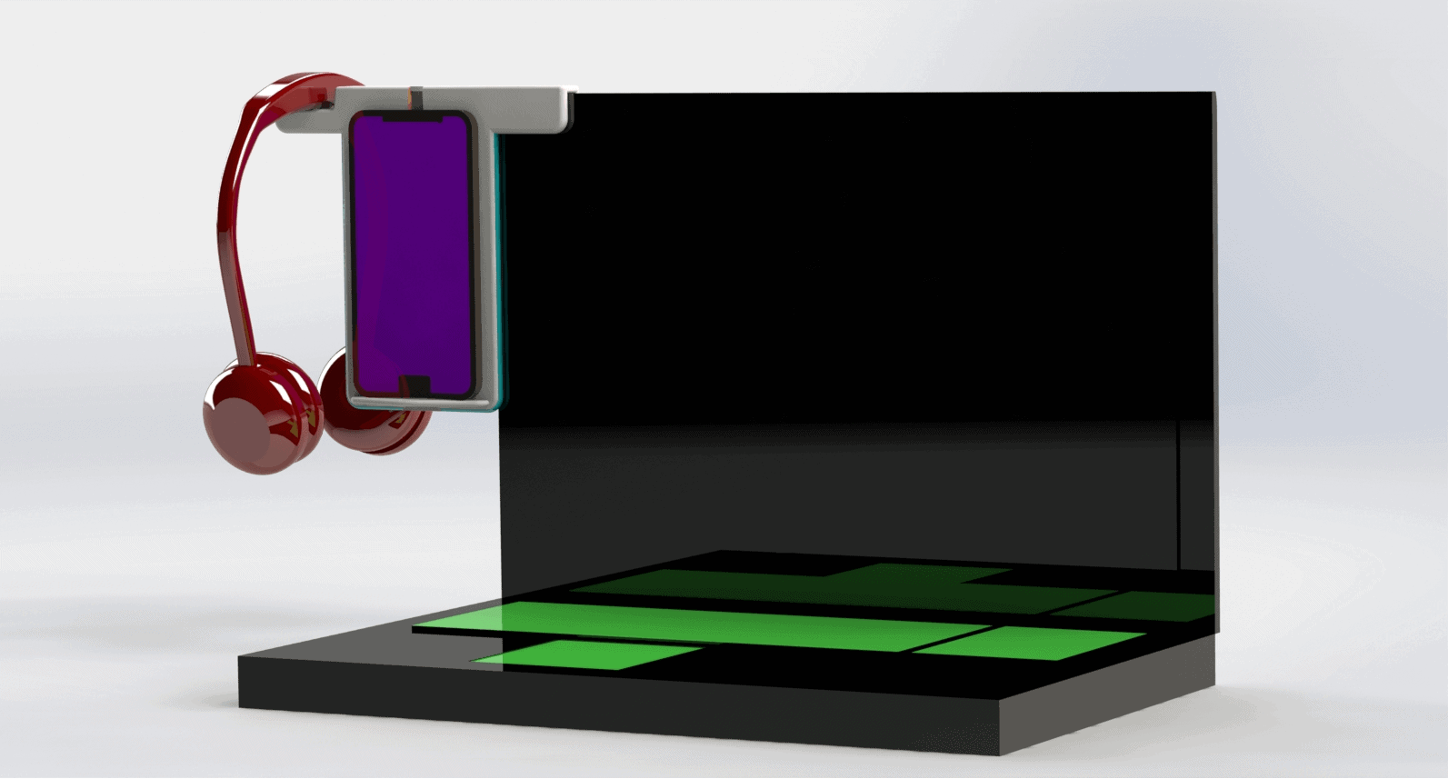
At this point, we are applying engineering assumptions as to how the physics of the system will react. What tools do we have at our disposal that will make us feel more confident about our initial assumptions? How can we analyze this design before building a prototype? Well, we can start by using some of the analysis tools built into SOLIDWORKS. In this case, I’ll use SOLIDWORKS Motion Analysis to apply gravity to our parts and see what type of reaction happens.
You can see in the video above that the Side Holster can’t stay attached to the laptop unless we add a mechanism that will keep it attached. There are a number of ways we can address this, such as adding a clamping mechanism or spring clip.
Keeping the Holster Hooked Up
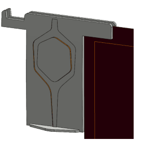
First, we tried using a spring clip because it’s a simple mechanism and keeps the number of components to a minimum. The spring force can be adjusted by changing the geometry of the component.
If the Holster were to become our design of choice for production, we’d be keeping our costs down by using fewer components. Having the ability to adjust the geometry to change the amount of force for our spring clip (essentially a leaf spring) allows us to iterate our design quickly and easily.
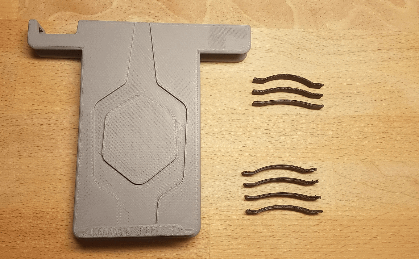
At this point, we produced some prototypes made to test our design, which gave us a tactile sense of the design. 3D printing our prototypes took a short amount of time further shortening the design phase. We used ABS material for the Side Holster and one set of spring clips and TPU material for another set of spring clips.
The Proof is in the Prototype
Before we tested out the Holster assembly, there’s a lot of information gained about our design from the physical prototype. The first thing we noticed was that the spring clips printed with TPU material were extremely flexible and would be unable to produce any real clamping force.
Next, we noticed that during the assembly process, it was difficult to seat the spring clip tabs into the notch due to the stiffness of the material. The material needs to be stiff enough to produce the amount of force necessary to counteract the reaction forces and moments caused by the weight of the smartphone and headphones. The tabs of the spring were cut down slightly to make the assembly process easier.
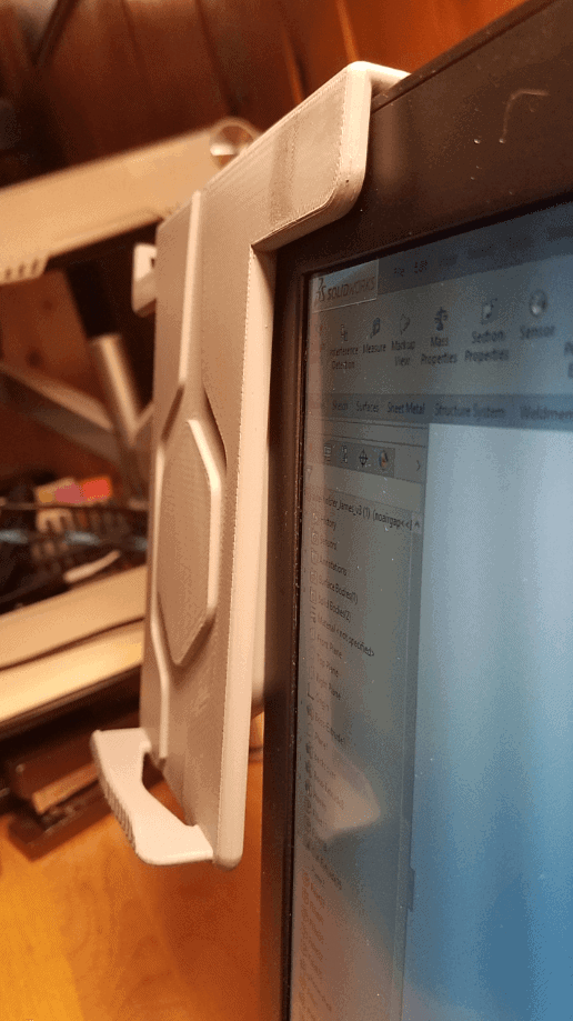
Lastly, we tested the Holster with and without the spring clips so we could verify our SOLIDWORKS Motion Analysis.
Without the spring clips, our Holster design immediately fell off the laptop when the headphones were put in place. When the spring clips were installed, we saw a much better result.
We noticed during our design testing that the spring clips causes the front of the Holster to lift away from the screen. This is unintended and will need to be addressed in our next design iteration.
By incorporating a virtual analysis tool like SOLIDWORKS Motion Analysis, we were able to catch possible design issues early and validate our findings from the physical test. Now that we’ve gathered valuable data from our physical prototype, we can start to plan our next steps. Stay tuned and subscribe to find out what design changes will be made after our design review.
Related Articles
Introduction to the Fisher Unitech Design to Manufacturing Series
Concept Creation | Design to Manufacturing Series (Part 2)
Overcoming Engineering Challenges | Design to Manufacturing Series (Part 3)
About the Author
 James Reeher has a Bachelor of Science in Mechanical Engineering from Cleveland State University and began using Solidworks in 2007. After many years as a Product Development Engineer in the industrial fitting, biomedical device, and LED lighting industries he joined the Fisher Unitech team in 2016. James is very interested in new technology and how different technologies can be applied to one another. As an Application Engineer, he enjoys helping customers learn how to leverage SOLIDWORKS to meet their needs and introduce them to other technologies that can help their business.