Tray Arrangement in GrabCAD Print
In GrabCAD Print, the Arrange tool has two options for automatic arrangement: “Arrange tray” and “Arrange project.” They work in the same way, except that Arrange tray will only arrange parts on the current tray, and Arrange project will arrange all parts across all of the trays. Here’s how they work:
Each part has a theoretical bounding box (cube shape) drawn around its largest dimensions. The parts are then placed on the tray(s) starting in the home corner (varies by printer type) from largest to smallest, giving a .25″ buffer around each bounding box. This does not adjust the orientation of any part. Because most parts are not cube-shaped, often parts can be successfully printed much closer together than the auto arrangement will place them. Click and drag to move parts around the tray, and right-click on parts to send them between trays.
How close can you place parts?
Unless a part is intersecting with another on a tray, you will be able to go into slice preview or print that tray, but it may fail while the tray is being processed. The reason for this is because the supports may be intersecting, but GrabCAD Print cannot know what the supports will look like until the tray is processed.
This is how close “Arrange tray” places these parts:
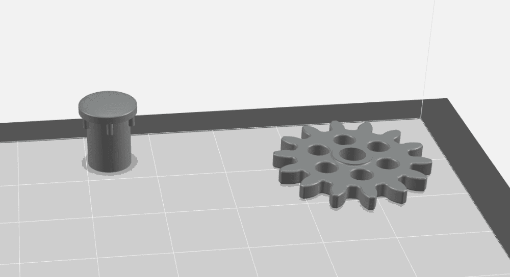
Once the tray has been sliced, the first support layer will be highlighted if the parts are too close to print:
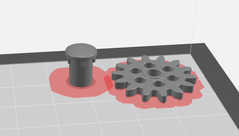
If you find the red areas on your print preview, the parts will need to be separated in order to print. You can simply move the parts around manually as needed or use the “Optimize” checkbox in the arrange command. Be aware the bounding box rule applies here as well, although with a much smaller bounding box.
Jeremy Marvin
Application Engineer
Computer Aided Technology, LLC