Using Area Hatch/Fill to Create Simple Decals in SOLIDWORKS Drawings
A couple weeks ago during a SOLIDWORKS Essentials class, an interesting question came up about adding basic decal-like features to a drawing. The student who asked was specifically hoping to create small white rectangles to cover up certain geometry that they wanted to hide on the printed drawing—things like proprietary components that they didn’t want the recipient of the drawing to know about. The Decal feature would not work in this case, as these markers were meant to be applied only to the drawing and to appear in front of any solid edges.
In general, I think suppressing superfluous features or otherwise removing them from the model is a more effective solution, but when this is not possible due to the complexity of the model or to time constraints, simply masking these details in the drawing in this fashion can be a decent fix.
Here’s the procedure we came up with.
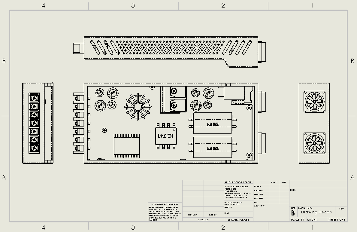
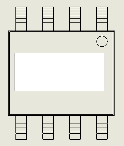
The drawing above highlights an enclosure for some electronics components. Let’s say that I want to share this drawing with a client so they can see the enclosure design, but I do not want them to see the type of amplifier used in the assembly.
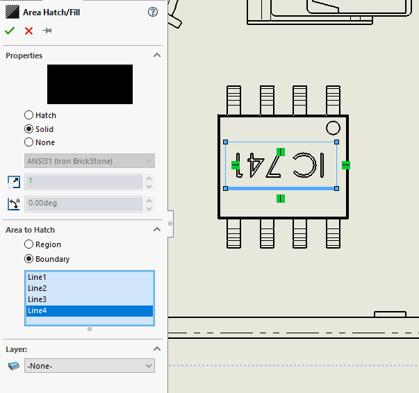
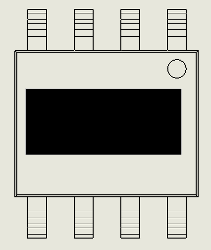
I can simply sketch a rectangle around the extruded “IC 741” text and use the Area Hatch/Fill command to generate a solid fill within the sketch lines. This has the effect of taking a black marker and shading over that portion of the drawing.
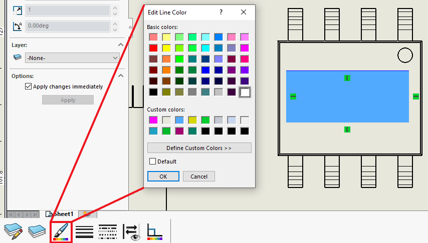
However, as I’d mentioned before, the student was looking to make the filled region white. The Area Hatch/Fill PropertyManager does not include any settings to control the color of the pattern, but the feature can be customized using the Line Color tool.
The Line Color dialog can be found in the Line Format toolbar. To edit my shading color, I can click the Area Hatch/Fill feature from the graphics area, launch Line Color, and pick a different color from the palette.
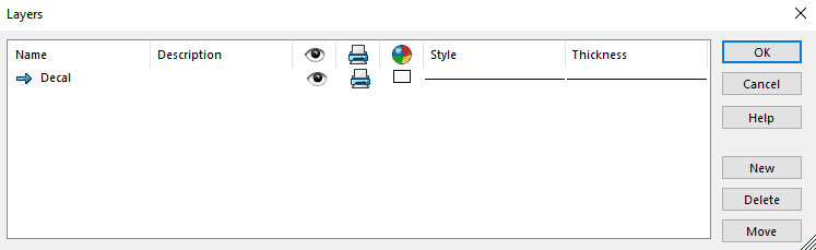
If several of these masks are needed, it could be more efficient to create a new layer with a white color. Each Area Hatch/Fill feature could then be assigned to this layer to ensure they all have identical properties.
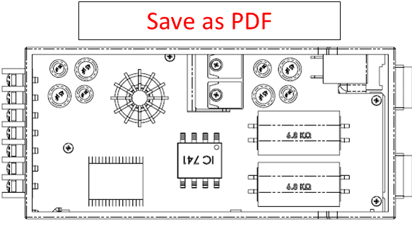
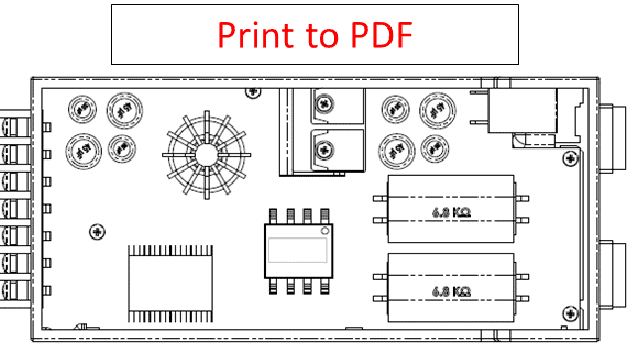
Once my “decals” are ready, I can export the drawing to a PDF. In order for the filled region to display properly, I need to use the Print command and choose to print to a PDF. Using Save As to create the PDF will not work: The edges of the model will still display through the shaded area, so the covered geometry will not be hidden. This is a known bug (SPR #662416), so until it is resolved I would advise against using Save As for this operation.
You can see the difference between the two outputs in the illustrations below. In the version created with Save As, the “IC 741” text is clearly visible despite the Area Hatch/Fill feature. In this case, the fill color is white, so the shape is not even visible on the white background of the drawing. If another color were used, the shaded area would at least be noticeable, but it would still not block out the geometry behind it. With the PDF created by the Print command, however, the white region is apparent and covers up the model edges.
I hope this method proves useful for you! Again, I feel that modifying the underlying part or assembly and removing details there is often a better practice than just brushing over them at the drawing level, but I’m sure there are some scenarios you might come across where the latter approach is appropriate. In those situations, feel free to reach out if you need any help.
Anthony Sandri
Application Engineer
Computer Aided Technology