Using Stratasys Insight’s Offset Tool to Improve 3D Printed Text
Text is extremely common on manufactured parts for instructional purposes, warnings, or simply labeling purposes. Sometimes the text is painted on or placed with a sticker but very often the parts have text built into the part itself. Sometimes when you try to print a part with integral text either raised out of the part or carved into the part, FDM printers can have trouble accurately recreating the text geometry. This occurs when the path of the text is too narrow to be able to fit two passes of material side by side.
We can create our parts with text in SOLIDWORKS and when the printer software slices the model, we get contours that look like the picture below.


Now we just need to add toolpaths to fill those contours with material. But these lines of material have a width of about 0.020” (0.51mm) and the printers want to enclose these lines of material into a loop, thus doubling the total width to 0.040”. Now if there is a portion of the text that is too narrow to fit both lines of material, the software will often fill as much of the letter as possible before turning around and going back to the beginning to finish the loop. This can leave large sections of the text unprinted and when this is stacked over multiple layers, can cause some very unattractive prints.
So how do we fix it? Well, besides temporarily removing the text from your CAD for the purposes of printing, our best bet is to try to modify it in Insight. The Insight software allows extreme flexibility and tunability of your 3D printed parts down to each layer and feature and is available with a Stratasys F370 and the entire Fortus line of Stratasys FDM printers. While there are a million and a half things you can do with this software, I’m going to focus in on just one tool to attempt to fix your text as quickly as possible.
What is this tool? It’s the offset tool!
But… what does the offset tool do? Well, you select a group of contours (in this case the text), set your offset, and voila! You now have a new set of contours that are a slightly different width. Even a small change of a couple thousandths can greatly improve the printer’s ability to reproduce the text. Lets take a look!

We will be working with a simple part that is just a plate with some raised text. Once it is sliced and toolpaths are generated, we can see to the right that there are a couple spots of the text that don’t have toolpaths generated properly.
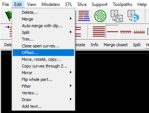
By going to the ‘Edit’ dropdown and selecting “Offset…” we access the Offset tool. The settings menu for this tool is simple with just four options. Offset direction, distance, and keep original are straight forward, however you can also select a group that you would like the generated offset to be added to during creation.
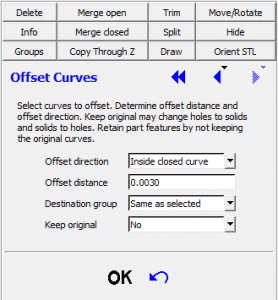

Now all we need to do is highlight the text, set our distance, and hit “OK”. Here, we can see by adding an offset of just 0.003” we greatly increase the printer’s ability to recreate the text!
And that’s all you need to do! I hope this was helpful and please check out our other Blogs for more great information for 3D printing, 3D Scanning, and SOLIDWORKS.
Nathan Fears
Application Engineer – 3D Scanners & SOLIDWORKS
Computer Aided Technology, Inc.