Valve Design using SOLIDWORKS Flow Simulation
A designer needs to understand how a concept design performs and then quickly, study design variations to come up with most efficient design. This factor alone makes Flow Simulation the perfect tool for engineers.
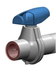
We will use a Ball Valve as an example. The user closes the internal volume of pipe using extrusions called lids. SOLIDWORKS Flow Simulation works with the SOLIDWORKS geometry, hence there is no need to define a fluid volume. Based on the enclosed region between the lids, the software is able to determine the calculation region.
I enjoy the preview the software gives as the solution is running. The preview allows you to look at the results while the calculation isstill running. This helps to determine if all the boundary conditions are correctly defined and gives the user an idea of how the solution will look even at this early stage. At the start of the run the results might look odd or change abruptly. However, as the run progresses these changes will lessen and the results will settle in on a converged solution. The result can be displayed either in contour-, isoline- or vector-representation.
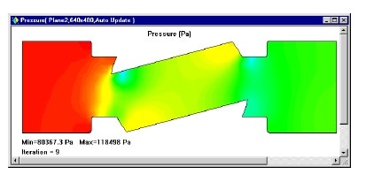
Once the solution is complete, there are multiple ways to understand design behavior.
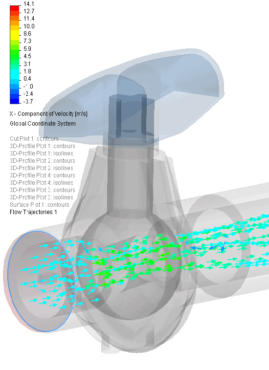
A cut plot displays the distribution of the selected parameter on a certain SOLIDWORKS plane. It can be represented as a contour plot, isolines, vectors, or as arbitrary combination of the above (e.g. contours with overlaid vectors).
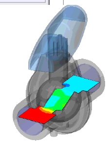
A surface plot shows the pressure distribution on all faces of the valve in contact with the fluid. You can also select one or more single surfaces for this plot, which do not have to be planar.
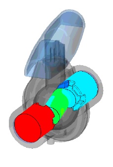
Using Flow trajectories you can show the flow streamlines. Flow trajectories provide a very good image of the 3D fluid flow. You can also see how parameters change along each trajectory by exporting data into Microsoft® Excel®. Additionally, you can save trajectories as SOLIDWORKS reference curves.
Since, SOLIDWORKS is parametic tool user can have multiple design configurations to check for different valve openings or shapes or flow rates. Once a test is run, to check for different variations of the same design, a user can set multiple tests by cloning the existing projects onto different configurations.
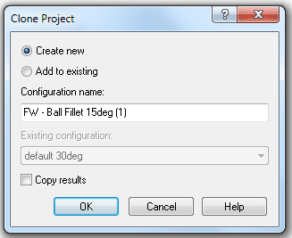
Now the Flow Simulation project we have chosen is added to the SOLIDWORKS project which contains the geometry that has been changed. All our input data are copied, so we do not need to define our openings or goals again. The Boundary Conditions can be changed, deleted or added. All changes to the geometry will only be applied to this new configuration, so the old results are still saved.
Imagine being the designer of this ball valve. How would you make decisions concerning your design? If you had to determine whether the benefit of modifying the design as we have just done outweighted the extra costs, how would you do this? Engineers have to make decisions such as this every day, and Flow Simulation is a tool to help them make those decisions. Every engineer who is required to make design decisions involving fluid and heat transfer should use Flow Simulation to test their ideas, allowing for fewer prototypes and quicker design cycles.
Rajat Trehan
Product Manager – Design Validation
Computer Aided Technology Inc.

 Blog
Blog