What Can't You Design In SolidWorks? #3
RC Hovercraft #3 – SOLIDWORKS Simulation
To review, I had 4 main design criteria for the Remote Control Hover Craft.
- Utilize the SOLIDWORKS and SOLIDWORKS Simulation Suite of software to develop and optimize the hovercraft design.
- The RC Hovercraft’s main components will be 3D Printed using the Stratasys UPrint.
- Easy to Assemble. I want to make the assembly as easy and as straight forward as possible with concise instructions.
- For purchased components, use low cost, off the shelf components including the electric motors, electronic speed control (ESC), batteries, and propellers.
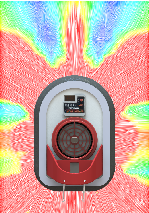
The next step of the design process is to verify using SOLIDWORKS Flow Simulation that the motor and propeller combination will provide a proper amount of air flow to lift the hover craft.
Flow Simulation provides an understanding of flow in an internal or external volume. Flow Simulation calculates flow with media including Gases, Fluids, Real Gases, and Non Newtonian Fluids. Flow Rate, Velocity, Pressure , Vortices, and many other parameters are calculated during the solution.
The following calculation with the provided manufacturer information was used to calculate the flow parameter boundary conditions for the simulation.
CFM = Cubic Feet per Minute = Volumetric Flow Rate
Mass Flow Rate = (Density) x (Volumetric Flow Rate)
Newton’s Second Law of Motion: Force = (Mass) x (Acceleration), or F = ma
F = ma = (Mass Flow Rate) x (Velocity), given a constant flow velocity
(i.e., constant propeller speed and pitch angle).
Velocity = (Volumetric Flow Rate) / (Area), where Area = (Pi) x (r^2), the
length of a propeller blade is a good approximation for the radius, r.
Thrust = (Density) x (CFM^2) / ((Pi) x (r^2))
Note: Keep track of your units!
The hover craft’s Flow Simulation was approached from an external analysis type. A volume was specified around the hover craft to capture flow into the inlet and out of the bladder, and its effect from the surrounding environment. A fan was used to provide the draw of air through the inlet into the internals of the hover craft. Parts of the hover craft were removed including the canopy cover batteries, and escs. These components are unnecessary for teh flow run and would increase computational time.

Air Velocity
Air Velocity Top
The results from the Flow Simulation run show a symmetric and even outlet pattern of flow from the Hover Craft’s “Bladder”. The parameters provided by the flow simulation suggest that the motor and propeller combination should be sufficient for lifting the craft.