SOLIDWORKS 2017 WHAT’S NEW: EVALUATING MODELS FOR 3D PRINTING – #SW2017
SOLIDWORKS 2017 has lots of useful new features. One of those hundreds of enhancements would be the Print3D FDM build analysis. This has been improved on from last year’s Print3D option which would allow you to see if your parts can fit in your printers build chamber and also help you save out the SOLIDWORKS file as a either an STL, 3D Manufacturing Format (.3mf), or an Additive Manufacturing File(.amf)
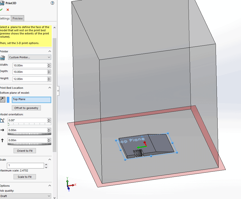
Now print3D has a set of build analysis features to help give you some info about issues the part could face during printing, before you waste time and money trying to print it. Once you start up the tool by going to File>Print3D… you can set the base plane for you part and build size of your printer, along with scaling, infill, and orientation.
Now we can jump on over to the ‘Preview’ tab and take a look at the analysis features.
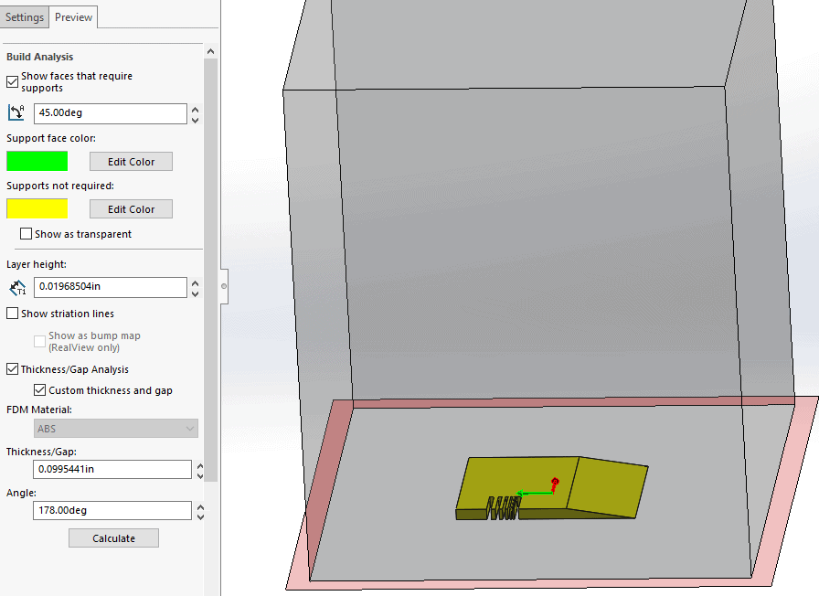
You will see that we can adjust the self support angle for when the start building support and also color code the part to visually show where support material will be needed.
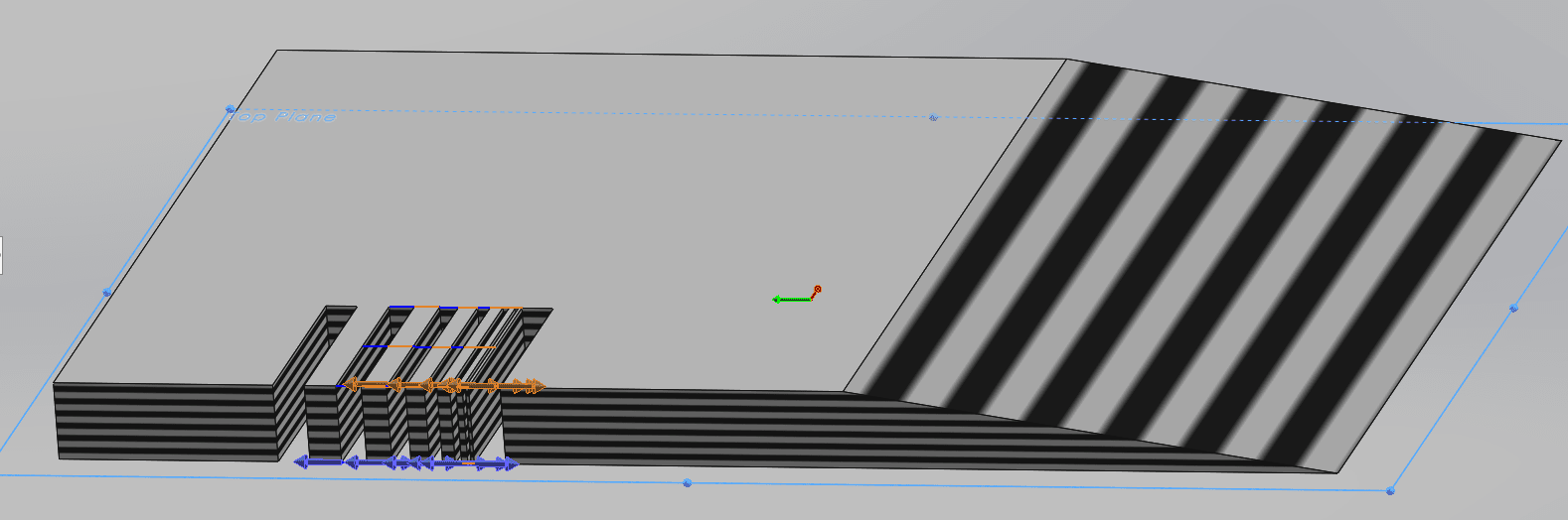
Then we can set the layer height that we will be running on the printer, with that info we can toggle on the striation lines to get a representation for how the layer lines will look on the part.
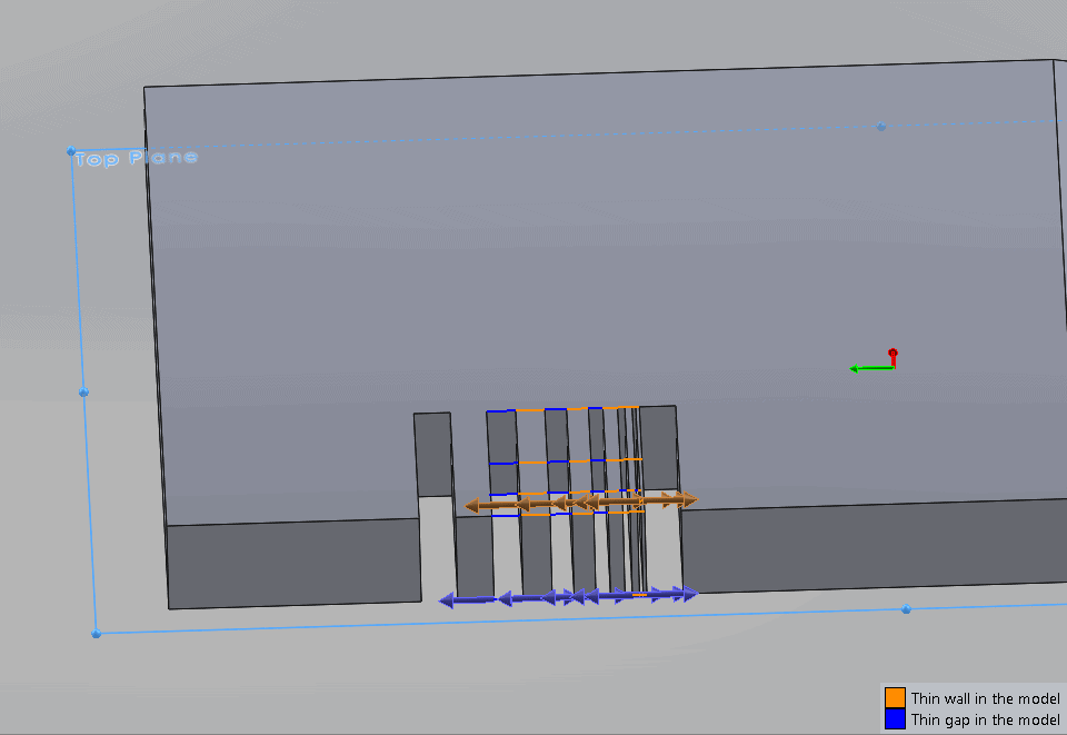
The last thing we can do is a simple check for minimum wall thickness and minimum gaps. Enter whatever values are your threshold for your printer setup and the program will show you the problem areas. Sections of model that are too thin will have an orange line on it and an arrow to help illustrate the direction you would need to expand the model to alleviate the issue. The blue lines show gaps between sections of model that are too small and could have issues with fusing. This also has arrows to show what directions to expand to correct it.
The SOLIDWORKS 2017 Print3D analysis is an improvement on what it used to be, however, it is by no means a full comprehensive analysis of your part. It works well for a quick overview and to point out any hidden thin features or gaps that might be hidden in your models somewhere, especially useful when working with other people models or STL files.
I hope this part of the What’s New series gives you a better understanding of the new features and functions of SOLIDWORKS 2017. Please check back to the CATI Blog as the CATI and MCAD Support Teams will continue to break down many of the new items in SOLIDWORKS 2017. All of these articles will be stored in the category of “SOLIDWORKS What’s New.” You can also learn more about SOLIDWORKS 2017 by clicking on the image below to register for one of CATI’s or CATI’s Design Summits.
Tim Crennen
CATI-MCAD Sr. Applications Engineer
Computer Aided Technology