SOLIDWORKS 2018 What’s New – Creating a Bounding Box – #SW2018
SOLIDWORKS 2018 What’s New – Creating a Bounding Box – #SW2018
SOLIDWORKS 2018 now allows you to create a Bounding Box around your parts! This Reference Geometry feature can be applied to multibody, single-body, and sheet metal parts to show the smallest box in which the part will fit, and automatically updates as the part features change, as bodies become hidden within the part, or as the part is flattened, folded, or unfolded. This feature is easy to use and adds informative properties about your part that can help in determining packaging requirements.

Previously, you could only add Bounding Boxes to cut list items, and the steps were less straightforward. To add a bounding box to your multibody, single-body, or sheet metal part in SOLIDWORKS 2018, simply follow the steps below:
- With your part file open, click Insert > Reference Geometry > Bounding Box
- The Bounding Box Property Manager will then appear, where you can select Options to “Include hidden bodies” or “Include surfaces.”
- Leave “Best Fit” selected in the “Reference Face/Plane” and click OK.
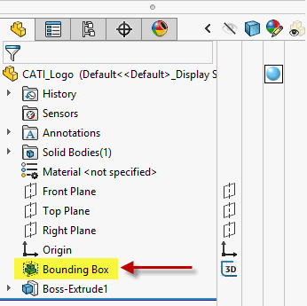
- The Bounding Box will appear as gray dashed lines around the part, and the feature itself will appear directly below the Origin in the FeatureManager Design Tree, as seen in the figure below.
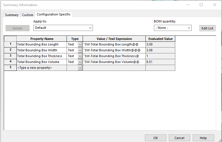
One of the biggest advantages of using Bounding Boxes for your part files is the information about the Bounding Box that SOLIDWORKS 2018 calculates. You can view Total Bounding Box Length, Total Bounding Box Width, Total Bounding Box Thickness, and Total Bounding Box Volume as seen in the figure below by clicking File > Properties and then choosing the Configuration Specific tab.
You can suppress/unsuppress, or hide/show the bounding box, which is useful when you do not want the Bounding Box to appear in a drawing or when you simply do not want it in the Display Area when editing other features of the part. Additionally, the Bounding Box feature can be modified by right clicking the Bounding Box feature and clicking Edit Feature. All in all, the Bounding Box feature in SOLIDWORKS 2018 allows you to quickly and easily find out useful information about their parts.
I hope this part of the What’s New series gives you a better understanding of the new features and functions of SOLIDWORKS 2018. Please check back to the CATI Blog as the CATI Application Engineers will continue to break down many of the new items in SOLIDWORKS 2018. All of these articles will be stored in the category of “SOLIDWORKS What’s New.” You can also learn more about SOLIDWORKS 2018 by clicking on the image below to register for one of CATI’s Design Innovation Summits.
Nicole Kelley
Application Support Engineer
www.cati.com