Make Your Mark on Injection Locations in SOLIDWORKS Plastics Simulation
Over time we learn new ways to do things. For example, I recently learned SOLIDWORKS’ preferred way of creating an injection location in SOLIDWORKS Plastics Simulation. Let’s take a look at SOLIDWORKS’ preferred method to create injection locations, the benefits of split lines, and the role split lines play in the process.
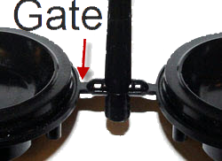
An injection location is where the cavity is filled from the runner system. Gates are the portion of the runner system that attaches to the injection location. Typically, the gate is cylindrical or conical, but many different shapes and options exist. For this example, we will assume that the gate is conical and intersects the part with a circular profile.
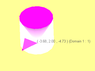
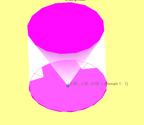
Until recently, I have always used a single nodal point for the injection location. This is not preferred method for a couple of reasons. Using one nodal point only injects using one adjacent cell. This causes issues like high shear rates, and negates the size of the injection location. Even if the user specifies an 8mm gate the injection only occurs over the size of one cell. This is problematic because that one cell is usually smaller than the specified injection location size. This is demonstrated below by the one cell highlighted in pink.
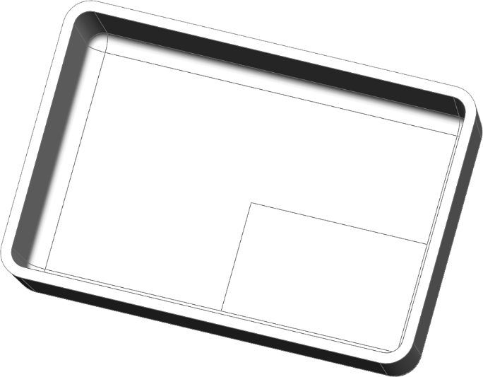
The second issue with using one nodal point is that the location you choose with the mouse jumps to the closest node, so between different meshes it is hard to choose the same location again and again. This can be resolved by using a “Split Line” command and adding an intersection on the model.
Because the split line creates a hard edge in the model, the mesh places a node at the intersection and makes repeatedly selecting the same location possible.
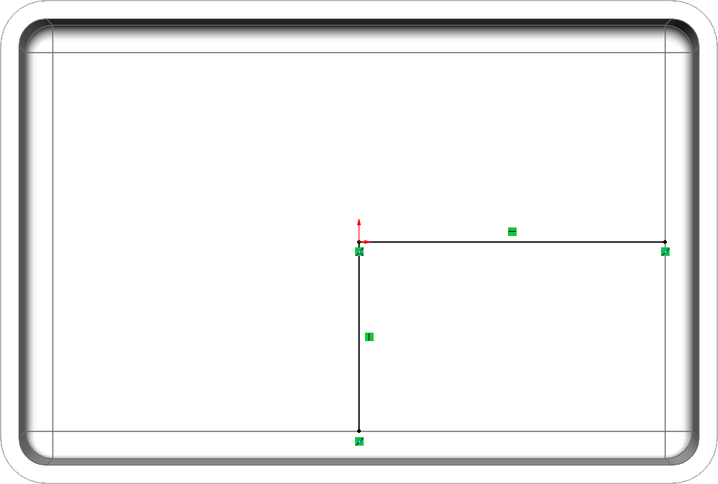
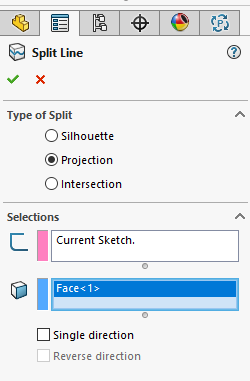
This resolved the inconsistency of location issue but still only selects one nodal location. The preferred method is to use a split line to mimic the area the gate would be in contact with the part.
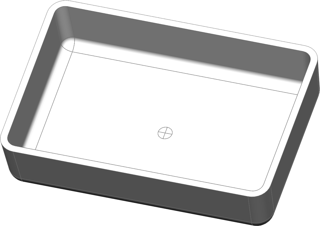
In our case, a circular profile of 4mm in diameter. An addition of a cross-hair is added in the sketch to pin point the center of our part.
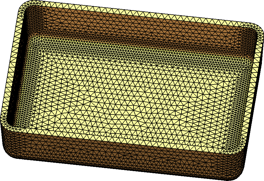
Once the split line is created, the resulting mesh with automatic refinement gives a series of cells that the injection location can be applied to.
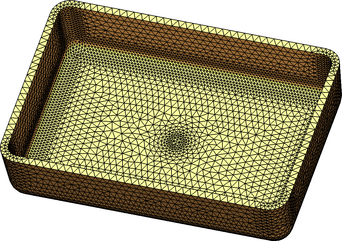
Specifying a 4mm injection location allows the software to distribute the injection over multiple cell reducing the shear affect and improving accuracy.
A simple modification to a standard practice that yields more accurate results. It is always good to learn new things. Let us know what type of gates you use, and how Plastics has improved your product, and mold design workflow.
 Robert Warren
Simulation Specialist, Elite Application Engineer
Dad, Husband, Mechanical Engineer, Jeep and Sasquatch Aficionado
Computer Aided Technology, Inc