SOLIDWORKS 2020 What’s New – Creating Alternate Position Views for Parts
In SOLIDWORKS 2019, the designer would need to create multiple model items or sheets to depict different configurations of a part. As SOLIDWORKS continues to improve, our goal is to also improve how effectively we can communicate designs in a collaborative environment. With SOLIDWORKS 2020, drawings get an important upgrade. You are now able to overlay an additional configuration in the same model view.
These modifications can give others a clear indication of different stages throughout the manufacturing process of a part.
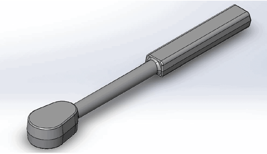
Let’s take, for instance, this ratchet body in its forged state:
In the SOLIDWORKS 2019 Release, you would have to create two model views to depict the configurations for the forged ratchet body and the machined ratchet body, as shown here:
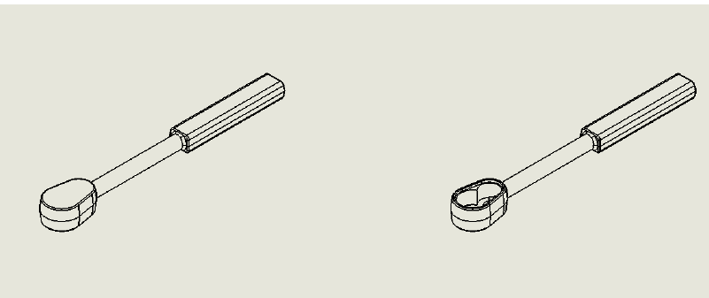
Notice how little new information is being communicated between each configuration, though we are still taking up quite a bit of precious real estate on our drawing sheet. Alternate position view, which now accompanies the other drawing views we use so regularly, can maximize what we communicate while optimizing space constraints.
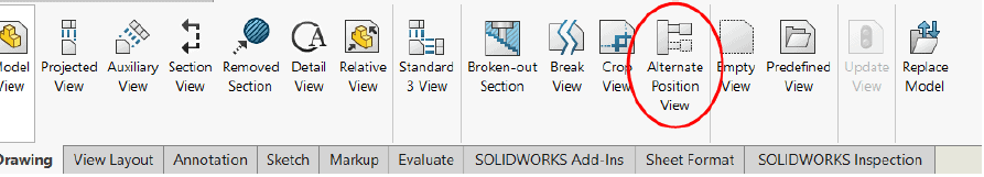
With a specific drawing view selected, simply select alternate position view and choose the configuration to be depicted with phantom lines. The top view is also shown to see how the center lines are automatically added within this view, as well.
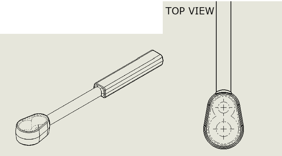
Of course, this view can be modified at any time to support additional configurations that may differ from the original.
SOLIDWORKS kept in mind how difficult it can be sometimes to call out the proper dimensions when there are several lines within a part. For this view, phantom lines will not be dimensioned although they are within the drawing. I found this to be even more helpful, as this view does not disturb my workflow. There are plenty of uses this feature can have in both part and assembly drawings, the choice is yours to see how this can work for you as well!
Design Innovation Month – October 2019
What is DI Month? We’re declaring October Design Innovation Month—again! It’s a month-long series of special events focused on what’s new in design and manufacturing technology. You’ll learn about enhancements in SOLIDWORKS 2020 that deliver new capabilities for improved performance, streamlined workflows, and a connected design ecosystem. Find out what’s new in 3D printing applications and 3D scanning to integrate into your design process. So, get ready to do things differently. It’s time to innovate! Learn more about Design Innovation Month and register for events here:
Jordan Kleinschmidt, CSWP
Application Engineer
Computer Aided Technology, LLC