Linear Patterning in SolidWorks
SOLIDWORKS has many pattern features that can be used to replicate geometry in your part and assembly files. Taking advantages of these pattern options in SOLIDWORKS can save you valuable time in both modeling and every time the file rebuilds. In this article, we will take a look at some of the options found within the linear pattern feature used in part files. Most of this information can also be applied to the other types of pattern features inside SolidWorks.
Linear Pattern Types
In the pattern property managers of the pattern features, you will see the option of patterning features, faces, or bodies.
Pattern Features
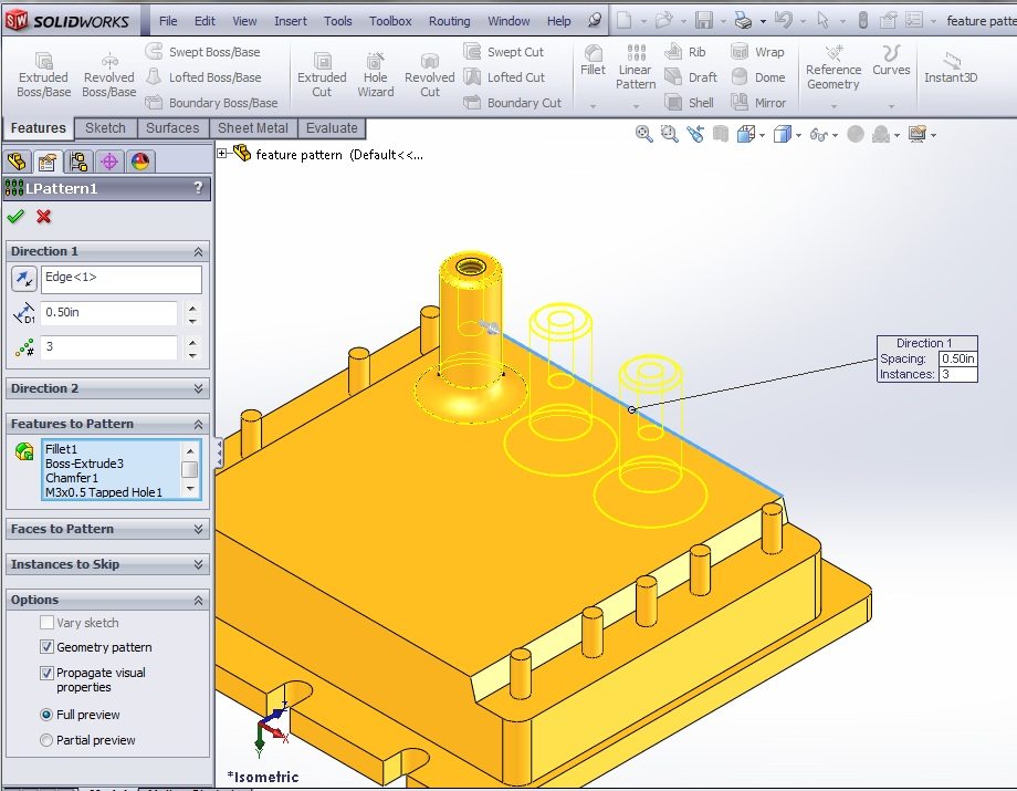
The “Features to Pattern” option will allow you to select one or more features in your part to pattern. In the example below, the boss- extrude, fillet, chamfer, and tapped hole features are all being patterned together in a single linear pattern feature.
Pattern Faces
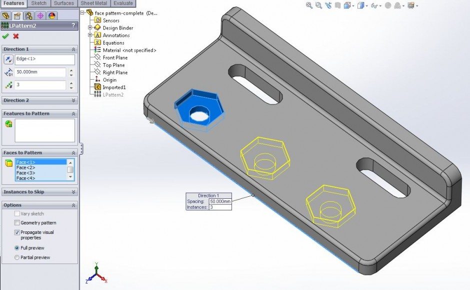
If your part file was created from importing geometry, perhaps generated in another CAD system, you will not have a list of features in the part’s Feature Manager. In this scenario, you will use the “Faces To Pattern” option. You will need to select all of the individual faces of the geometry you want to replicate. In the example below, 8 faces were selected to identify the seed geometry.
Pattern Bodies
The “Bodies to Pattern” option is fairly simple. This allows you to pattern an entire solid body. The results can be merged if the new geometry overlap, or can be disjoint like the part below.
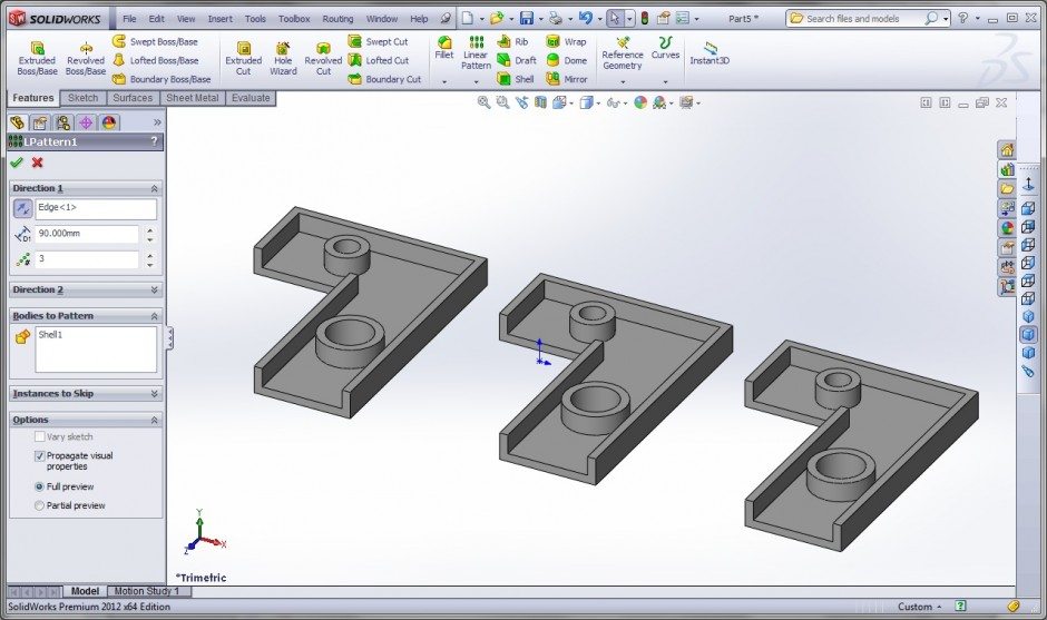
Patterning bodies in a solidworks part file. This results in 3 disjoint bodies.
Pattern Options
We will now focus on the “Geometry Pattern” and “Vary Sketch” options found at the bottom of the Linear Pattern property manager.
Geometry pattern
The “Geometry Pattern” option is often overlooked. This check box can be found at the bottom of the pattern options. Geometry Pattern can usually save rebuild time of the model when enabled. There are some specific situations where it cannot be applied and other situations where it can be used to generate geometry that actually differs from the seed features.
The geometry pattern option controls whether the patterned instances are being “solved”, or just copied. With Geometry Pattern turned off, items like the feature end conditions are being calculated for every new copy of the feature. If you have an “offset from surface” end condition for the seed feature, then all the other instances are solving how that offset geometry should be created. With the Geometry Pattern turned on, these calculations are ignored and each pattern instance is an exact copy of the original.
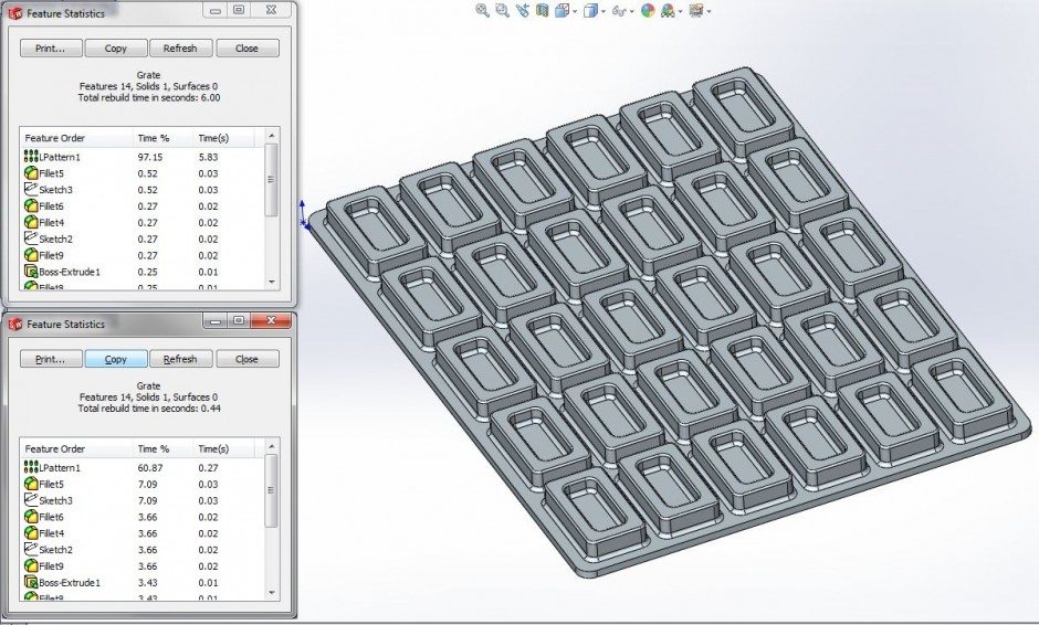
Here is an example showing the rebuild time variation when geometry pattern option is used. In this case, patterning the 8 features that make up the seed geometry with Geometry Pattern enabled can save approximately 5.5 seconds every time the part rebuilds.
You can determine rebuild time of your part by going to the Tools menu, and selecting “Feature Statistics”. Comparing rebuild time with Geometry Pattern on and off, we can see that we save approximately 5.5 seconds when we have Geometry Pattern enabled.
In order for the Geometry Pattern option to work, all of the faces generated by the pattern must be exactly the same. In this example below, the upper left rectangular extrusion is the seed feature. It creates the outside face that merges into the outer face of the base feature. All of the patterned instances will not merge into the base. This means that the newly created geometry will not have the exact same faces as the seed geometry. In this scenario, the pattern feature will fail if the Geometry Pattern option is enabled.
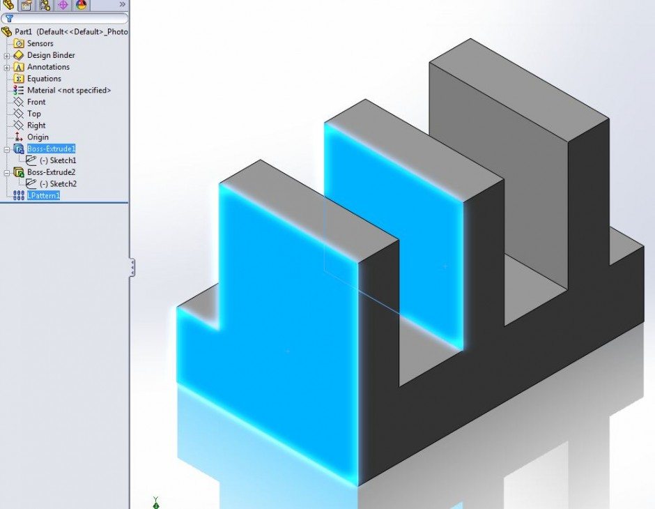
The two blue faces of this part are not identical. Geometry Pattern cannot be applied in this scenario.
In the next example, the cut-extrude has the end condition set at “Offset From Surface.” With Geometry Pattern turned off, the end condition is calculated for the new instances, shown at the left. At the right, the geometry pattern is turned on and producing identical geometry as the seed feature.
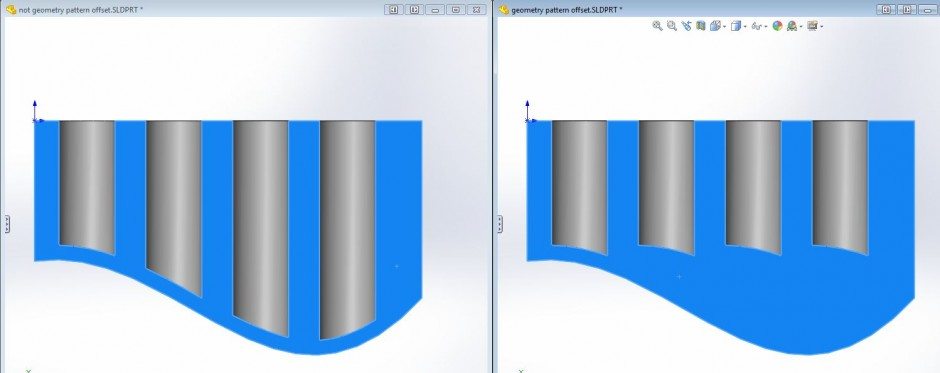
Having the feature “solve” by disabling Geometry Pattern can allow the patterned geometry to differ from the seed geometry. At the left, you can see what happens if Geometry Pattern is turned off.
Vary Sketch
Another option that allows the patterned instances to have different geometry than the seed feature is using the “Vary Sketch” option. This allows the initial sketch to be solved individually for each of the patterned instances. You will need to configure the initial sketch’s relations in a manner that will allow variation in the sketch.
In this sketch, the width of the slot is determined by the tangent relation to the outside diagonal construction lines. As the 45mm dimension increases, the width of the slot also increases. In order to apply the Vary Sketch option, this linear dimension must be selected to identify the direction of the pattern.
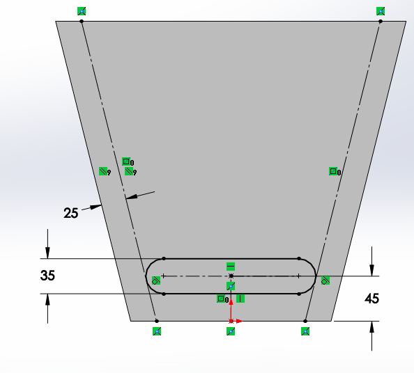
The sketch relations are configured so that the slot will increase in width if the 45mm dimension increases. This is required in order to take advantage of the Vary Sketch option.
On the right, you can see how the slots change width as they are being patterned vertically. This is due to the Vary Sketch option causing the sketch to be solved for each patterned instance.
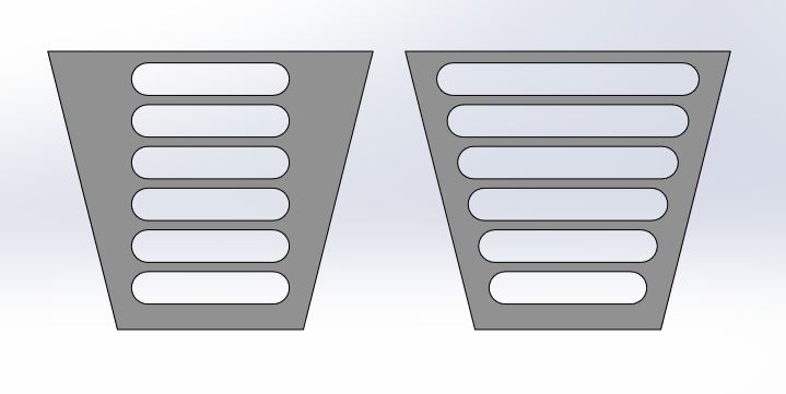
The Vary Sketch option is turned on for the example at the right.
Use this information on Linear Patterns to save some time and make your solid modeling more efficient.
Read More about Linear Patterning in Solidworks, or sign up for a SOLIDWORKS training class.
Author: Greg Buter