What Can't You Design In SolidWorks? #2
RC Hovercraft #2 – SolidWorks
To review, I had 4 main design criteria for the Remote Control Hover Craft.
- Utilize the SOLIDWORKS and SOLIDWORKS Simulation Suite of software to develop and optimize the hovercraft design.
- The RC Hovercraft’s main components will be 3D Printed using the Stratasys UPrint.
- Easy to Assemble. I want to make the assembly as easy and as straight forward as possible with concise instructions.
- For purchases components, use low cost, off the shelf components including the electric motors, electronic speed control (ESC), batteries, and propellers.
I proceeded forward with the design of the Hovercraft using SOLIDWORKS 3D mechanical design software. SOLIDWORKS allowed me to quickly develop and execute a first pass design, utilizing Multi-Body Parts, In context Assembly Modeling, Sketch Pictures, Fastening Features, Interference Detection, and several other standard options. All of this came together in an initial design that meets the above criteria.
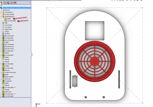
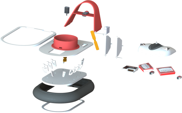
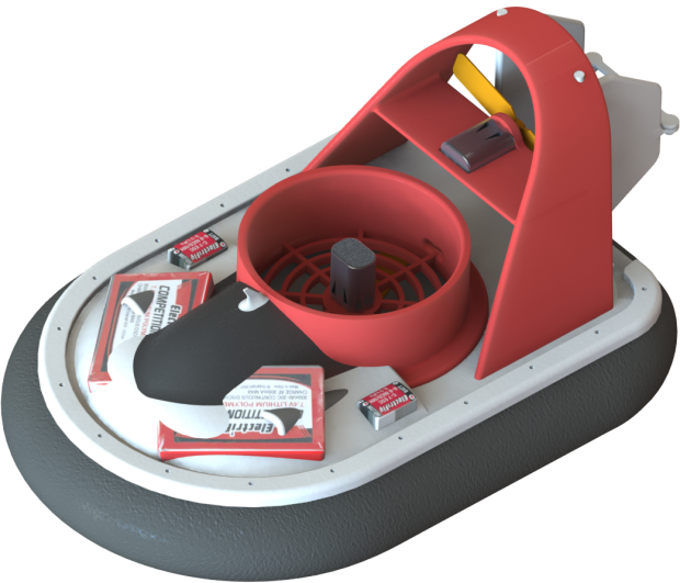
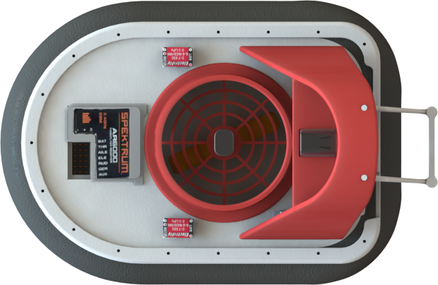
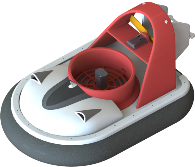
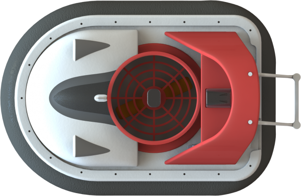
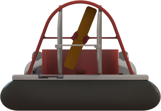
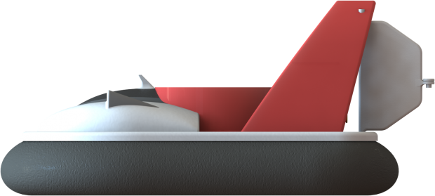
The design started with the Top Plate part that houses the downward facing fan assembly and gives the craft its overall dimensional size. I kept the craft under the 8″ by 8″ tray size of the Stratasys UPrint 3D Printer. The part consists of multi-bodies; one for the plate and the other for the fan housing. These bodies have minimal tolerance so they are a snug fit when pressed together for final assembly. This design criteria is so that if the propeller needs to be serviced later total dis-assembly of the craft does not have to take place. Simply pull the fan unit upward out of the top plate.
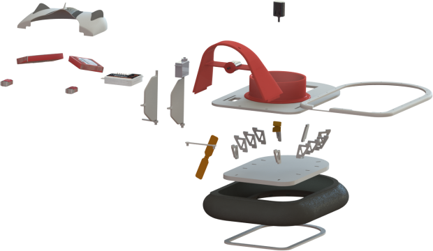
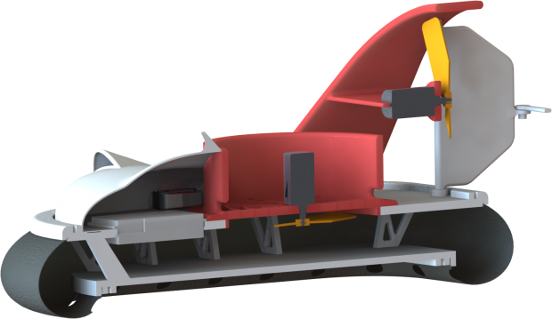
The chassis continues with a bottom plate and separating ribs. The chassis is hollow as the air needs to fill this cavity before exiting out of the skirt. The skirt is intended to be a bicycle inner tube cut to size with holes cut around the inner bottom portion allowing the air to escape. The skirt will be held on by two fastening plates and standard hobby store machine screws.
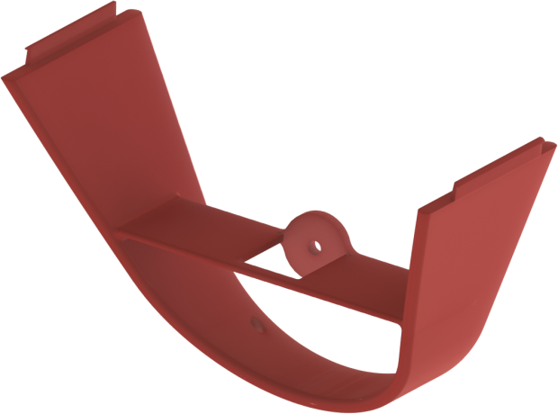
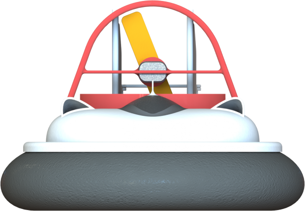
The back cowling snaps into place with a Snap Hook. The Fastening Feature command was used to create this geometry. The Snap Hook will allow for ease of assembly, and the cowl contains a cross bar with built in motor mount sized for a 9V-11V brushed can motor. The Cowling and Top Plate will make up the mounting location for the dual rudder system. The system is driven by an S75 Nano servo available at most local hobby shops.
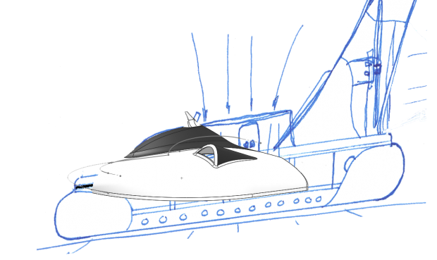
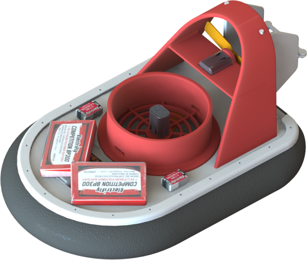
The canopy will cover all of the electronics including the Receiver, two Electronic Speed Controls (ESC), And two Li-Poly 300MAH 11.1V Batteries. One ESC and battery per motor. I originally set out utilizing the Sketch Picture and Surfacing to create the canopy structure. This worked out well, however at this time I did not have the electronics in the full assembly. When trying to accommodate the electronics under the first variation of the canopy I visibly had interference. Luckily utilizing in-context editing and having a well planned design intent, the changes to the canopy allowed for an easy and quick change.
There is still much to do with the modeling aspect, but for now I have a good working start to the project and a starting point to investigate the flow and stress characteristics of the design. The next step is to utilize Flow Simulation to verify the lift ability of the motor and propeller combination for the lift fan and the rear facing fan assembly.

 Blog
Blog 