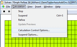
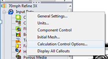
1. Make sure we are saving the steps during the Flow solution. Open the “Calculation Control” dialog. This is accessible from the flow feature manager, command manager, and the solver menu window:
1a. Choose the saving tab and enter how often you want to save results.
1b. The individual iteration results will be saved in your Flow folder for each iteration as “r_XXXX.fld“
These are individual result sets which will be referenced to create your animation.
Be careful: this is a good way to fill up your hard drive for larger models with small times steps.CONTINUE READING:
2. Solve the flow model.
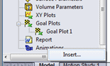
3. Load the results (last iteration is default) and create a plot that you want to animate, such as a cut plot or surface plot.
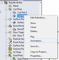
4. To begin creating the animation, either right click “Animation” in the feature manager and choose Insert or right-click the desired result set to animate such as a cut plot and choose Animation.
5. Once the animation pane appears, you will want to drag the study “control point” all the way until the start of the animation (to the left).
6. To bring the individual time frames/iteration in, you will then click the “Movie” icon.
6a. Enter the desired duration of the animation, and click “Next.”
6b. Choose rotation or not; you can still rotate the model using control points and views later if you choose “no” here. The rotation will add key frames for a simple rotation about the global axis. Click “Next.”
6c. Select “Scenario” to animate multiple timesteps. Click “Next.”
6d. Choose “Uniform” or “Proportional” and select the start and finish from the sliders if you don’t want to include all the timesteps/iterations results.
6e. Now you will see a “control point” for each iteration brought into the animation.
7. To determine when the features are displayed in the timeline, you can insert and drag the “control points” for that feature.
7a. To choreograph different plots, you can adjust “control points” for the individual features to begin and end at different times or overlap etc… (see the video we phase out the mesh cutplot then phase in the flow stream cutplot.)
7b. To change the view during the animation, you can place “control points” in the animation pane to move from one view to another. First, you must right click the project name and unselect “Lock Orientation.” Each control point is a specific view orientation, and when they are connected, the model moves from one view to the next dynamically. To adjust the orientation at a “control point,” drag the slider bar to the point and adjust the model view. (See the video below).
8. Now you can hit the play button and the view orientation will change based on your view “control points.” In addition, your feature plots with “control points” will update based on the solver iterations. You can also save the animation as an .avi file by clicking the record button. This can be useful since the frames can take some time to load.
Watch the video below a couple times and you will see that it’s a pretty quick process.