Optimizing Your CAD Software for FDM 3D Printing
Get the Best 3D Print with Minimal Waste
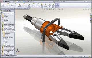
Whether modeling in SOLIDWORKS, Creo, NX, or any other Computer Aided Design (CAD) software, bringing your design to life is easy with a 3D Printer, but it all starts with an STL file. Here are some tips to consider for your next design, to get the best possible 3D Print, while reducing material waste.
Tip #1: Watch the Walls
The width of thin walls should be designed as a multiple of the filament bead width, bearing in mind the number of perimeter toolpaths (aka “contours”). For example, the standard configuration for Stratasys professional 3D printers produces one 0.5mm perimeter bead (with infill rasters in between). Very thin walls should be either 0.5mm OR 1mm wide. Any width in between is likely to be undersized and/or inconsistent.
Tip #2: Mind the Gaps
Most machines (or slicing software) have a minimum size for infill rasters, which might result in airgaps within thin walls. For the example machine above, a 1.3mm wall isn’t quite wide enough to infill, so it’ll print as two thin flimsy walls side by side. In this case, a 1mm wall would be more rigid, despite being narrower, because the two beads would be fused.
Also be sure to remember that STL files (sometimes referred to as “Standard Tessellation Language”) are faceted; meaning they contain no curves! So, when sliced into layers, every ‘circle’ is actually a polygon. Thus, exterior curves will always be slightly oversized and internal curves will be slightly undersized. The results can be improved by tweaking the STL export settings in CAD (use the “fine” resolution or better); just be consistent. While designing, consider defining custom oversized hole standards or undersized library features, in order to get consistent fits for pins/holes.
Tip #3: Account for Orientation
Whenever possible, build cup-shaped parts open-end-up, to avoid unnecessary support. But when that that’s not possible, consider that most machines can bridge short horizontal spans without building support underneath. To minimize use of support material and speed up prints, stay out of the ‘support zone’ between 0° (horizontal) and 45°.
Also include chamfers or fillets to inside corners whenever possible, to reduce the length of horizontal spans (and the likelihood they will require support). For example, a 1” diameter cup printed upside-down might result in a LOT of support material used. But adding just a 1/8” chamfer reduces the unsupported “ceiling” to just ¾”, and might eliminate the need for support altogether.