Rocket Science Is Easy!
I am sure at least once in your lifetime you have heard someone say “it’s not rocket science”. Well for those of you who say that phrase, I say “Rocket Science Is Easy”. At least for model rockets. One basic principle exists that all backyard rocket designers hold true. Keep the Center of Pressure (Cp) below the Center of Gravity (Cg). That’s it! That’s all that every Junior rocket scientist needs to know. Yes there are more calculations and design considerations that go into a rocket, but the most important are the Cp and Cg relative locations for stability.
Let’s take a step backward for the moment and introduce a rocket in its simplest form. A rocket consists of three basic components, the nose cone, the body, and the stabilizers (fins).
A further understanding of the rocket’s components will aid in material selection. Three basic nose cone configurations exist. The cone, hemisphere, and ogive.
Generally the body is a long slender tube with a constant cross-section, but this is not a hard rule. Stabilizers are available with varying shapes and sizes, but are commonly a thin component with a rectangular or tapered planform.
The material choice for the components is affected by two main design criteria, weight and strength. The nose cones from commercially available kits are usually blow molded plastic, which is light weight and strong for its application. Usually home developed models us a carved or turned balsa nose cone. Balsa is a light but strong wood with a density less than cork. Balsa is often used as the core material in composites, and for flying model aircraft. The body tube is generally cardboard, or thin plastic. Stabilizers are typically balsa sheets cut to size, however some Ready To Fly (RTF) rockets have an injection molded tail section combining all the stabilizers into one piece.
What goes up must come down!
Since rockets are not exempt from this rule a recovery system is required to bring the rocket back to earth safely. For a model rocket the recovery system specification is largely dependent on the weight of the rocket. Recovery systems range from a tumble system (light weight), streamer system (medium weight), and a parachute recovery(heavy weight). Exotic recovery systems also exist such as auto-rotation or, glider systems.
The Motor
Model rocket propulsion comes in many forms. Compressed air, water, black powder (solid fuel), and many others. The model rocket design will focus on the use of the black powder rocket engine. These engines are commercially available from local hobby shops, and come in standard sizes. Classification of the model rocket engines and their parameters are published by the manufacturer.
The cut away below shows the standard layout of a single stage black powder rocket engine.
The motor consists of a cardboard housing containing 5 internal sections. The internal sections of the motor directly relate to the flight path of the rocket. The clay nozzle directs the flow of the black powder propellant as it burns. The burn cycle of the propellant is the thrust phase of the rocket’s trajectory. When the propellant is done burning the delay composition starts to burn slowly creating smoke. This is the coast phase of the rocket’s trajectory, and the rocket is still traveling upward from the momentum generated from the thrust phase. When the delay composition is done burning it ignites the ejection charge. The ejection charge pressurizes the motor housing expanding the clay cap. This ejection charge pushes the nose cone out of the body tube, and deploys the recovery system.
The Design
This project started with my 5 year old son asking if we could build a rocket out of a plastic tube(center tube of a plotter paper roll) he found in the basement. The tube was 36″ long, 53.2 mm in diameter, with a 1 mm thick wall. Based on the measured dimensions, metric units were used for the rest of the design. Employing SOLIDWORKS as the design software reduced the time from idea to launch pad. Deciding what rocket to make took the most time. After looking at dozens of pictures of full size and model rockets we decided on making a scale model of the German V2, brain child of rocket scientist Whernher von Braun. When most of us think of a rocket we picture the classic cigar shaped body with four large fins.
The first step to designing this rocket was to determine what materials to use. Since the main body tube is plastic, it only made sense to keep the theme. Fortunately I have access to several 3D printers at 3DVision Technologies and decided to use the Stratasys uPrint SE Plus to rapid prototype the design.
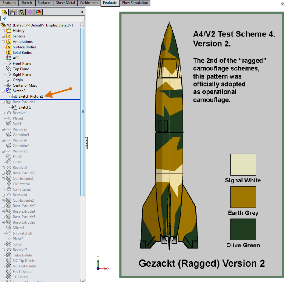
I found an image of the V2’s side profile on the internet and used this as a basis to scale the model. Because I am working with the fixed dimensions of the tube this made it easy to set up the model. I used the sketch picture option in SOLIDWORKS to import and scale the image to match the given tube diameter of 53.2 mm. The original V2’s diameter is 1.65 m, giving the model rocket a scale of 1/31.
To create the rocket I started off by extruding the body tube to match the sketch picture. This lead to the tube being 140 mm in length. Since the parts are being created on the uPrint a clearance of 0.005″ or 0.127 mm was used to create a “slip fit” between parts.
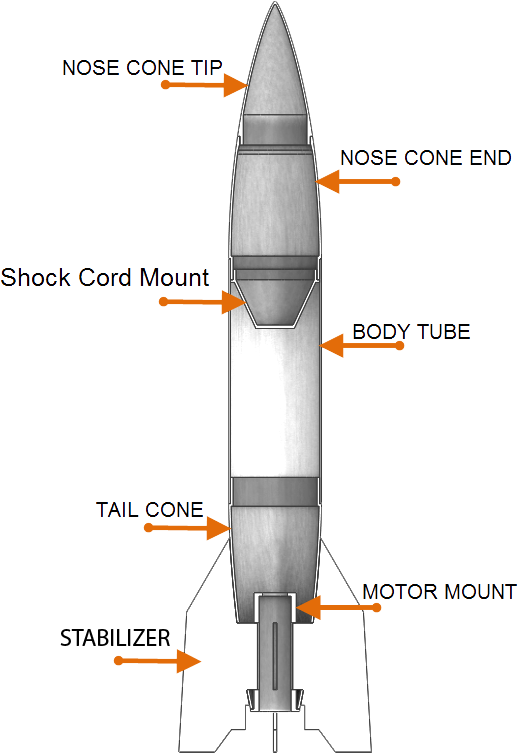
A multi-body approach to the rocket proved very useful, and made generating the geometry easy and quick. To fit the geometry in the build envelope of the uPrint, the nose cone was divided into three parts, the nose cone tip, nose cone end, and the shock cord mount. Dividing the nose cone allows for the nose cone to be printed in a vertical position, which leads to a very smooth surface. The tail cone and motor mount include holes for the stabilizers to be inserted. This method automatically aligns the stabilizers to a vertical position 90 Degrees to each other, and fixtures the motor mount in the tail cone.
The motor mount is designed around a standard 18 mm motor size keeping the scale aspect of the tail cone.
The nose cone tip, nose cone end, and shock cord mount will all be affixed together using a Cyanoacrylate glue (CA), creating the nose cone sub-assembly. The body tube, tail cone, stabilizers, and motor mount make up the second sub-assembly of the rocket. The nose cone sub-assembly, and body sub-assembly will be attached together through the use of an elastic shock cord. The parachute recovery system will be attached to a midpoint on the shock cord.
Before the design can be finalized we need to discuss the Center of Pressure, Center of Gravity, and Performance calculations. These calculations will define the rocket’s stability and flight characteristics.
Don’t miss the next blog in this series titled “Rocket Science is Easy! The Calculations“.